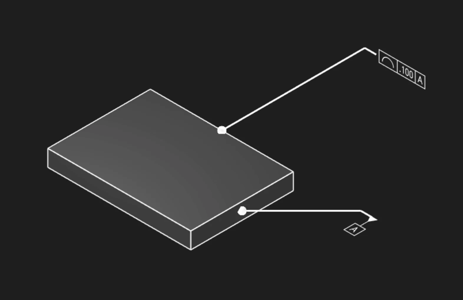
Profile
Profile controls how far selected edge geometry may vary from its ideal outline. Use Profile when a curved or contoured edge needs a tolerance zone that follows the intended shape instead of a simple linear distance.
Edges
Select one or more edges to control. Profile currently applies to edge geometry, so choose the outline, curve, or boundary whose shape tolerance should travel with the model.
Tolerance
Set the allowed deviation from the ideal profile in the current unit system. The tolerance defines the size of the profile zone around the selected edge.
Datums
Add datum references when the profile tolerance should be evaluated relative to a datum reference frame. You can include primary, secondary, and tertiary datum labels.
Precision
Choose how many decimal places to display in the annotation. This affects the callout text, not the underlying tolerance value.
Frame Position
Place the feature control frame relative to the leader arrow. Move it far enough from the selected edge that the annotation stays readable.
Frame Plane
Choose the plane used to display the annotation frame. Use XY, XZ, or YZ when you need the
callout to face a predictable viewing direction.
Leader Scale
Adjust the visual size of the leader dot. Increase this when the selected edge is small or the annotation is difficult to see.
Font Size
Set the model-space height of the annotation text. Use explicit units when you need the callout to scale predictably with the part.
Are you interested in code?
Zoo Design Studio writes KCL behind the scenes. A Profile annotation uses gdt::profile with one
or more selected edges and a tolerance.
Want to find out more about the gdt::profile function?
Check it out in our KCL docs.