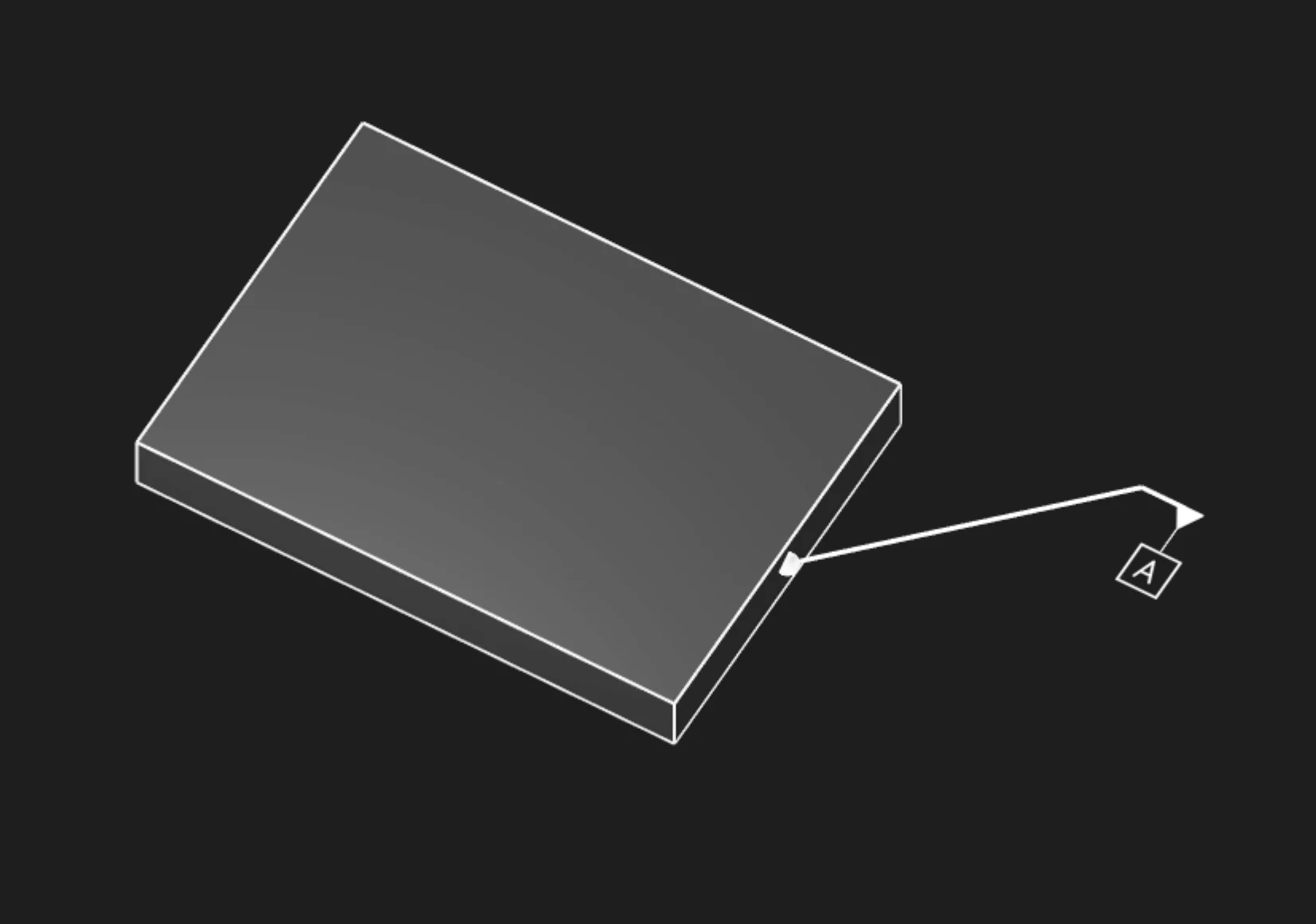
Datum annotations establish reference features that form the datum reference frame (DRF) for geometric dimensioning and tolerancing. Use Datum annotations to identify planes, axes, and points that constrain part degrees of freedom and serve as measurement references for related tolerances.
Options
Faces
Select the face or faces that define this datum feature. This is the real geometry from which the theoretical datum reference is derived.
You can use:
- Planar faces - Define datum planes (most common)
- Cylindrical faces - Define datum axes
- Spherical faces - Define datum points
Name
The datum label - typically a single capital letter:
- "A" - Primary datum (constrains the most degrees of freedom)
- "B" - Secondary datum
- "C" - Tertiary datum (fully constrains the part)
- "D", "E", etc. - Additional datums as needed
Each datum label must be unique within the part.
Frame Position
Where to place the datum symbol (the letter in a square box) on the face, as [X, Y] coordinates.
Best practices:
- Place near the center of large planar datums
- Keep away from edges to avoid crowding
- Align multiple datum callouts for clarity
Frame Plane
Which plane to orient the datum symbol in:
- Standard planes (XY, YZ, XZ)
- Face-aligned
Leader Scale
Scale factor for the leader line connecting the symbol to the feature. Increase for better visibility.
Font Point Size
Font size in points for the datum label.
Font Scale
Overall scaling for the entire datum symbol (frame and text).
Datum Reference Frame (DRF)
3-2-1 Datum Scheme
The most common datum scheme uses three datums to fully constrain a part:
Datum A (Primary): Planar feature, constrains 3 degrees of freedom
- Translation perpendicular to plane (1 DOF)
- Rotation about two axes in the plane (2 DOF)
- Remaining: 3 DOF (2 translations in-plane, 1 rotation about normal)
Datum B (Secondary): Planar or linear feature, constrains 2 additional DOF
- Typically perpendicular to Datum A
- Constrains 1 translation and 1 rotation
- Remaining: 1 DOF (1 rotation or 1 translation)
Datum C (Tertiary): Planar, linear, or point feature, constrains final DOF
- Completes full 6-DOF constraint
- Part is fully located in space
Datum Feature Simulator
In physical inspection, datum features contact simulated datums:
- Planar datums: Contact surface plate or gage plane (high points contact)
- Cylindrical datums: Contact expanding mandrel or precision bore
- Point datums: Contact spherical or hemispherical contact
The contacted high points or surfaces define the actual datum from the imperfect real feature.
Design Applications
Machined Part Setup
Define datums matching machining setup:
- Datum A: Primary clamping surface (largest stable face)
- Datum B: Side locator (perpendicular registration)
- Datum C: End stop or pin location (final constraint)
Assembly Interfaces
Specify datums at mating surfaces:
- Mounting flange: Datum A (planar face)
- Locating bore: Datum B (cylindrical axis)
- Keying feature: Datum C (slot or pin)
Inspection Setup
Define datums matching CMM or gage setup:
- Datum A: Part seating plane on CMM table
- Datum B: Alignment feature (bore, edge)
- Datum C: Rotation constraint (pin hole, flat)
Datum Selection Guidelines
Stability
Choose datums that provide stable, repeatable contact:
- Large, flat surfaces for planar datums
- Precision-machined features, not as-cast or as-formed surfaces
- Features with tight form tolerances (flatness, cylindricity)
Functional Relevance
Select datums matching part function:
- Assembly mating surfaces as datums
- Mounting or locating features
- Critical dimensions measured from functional datums
Manufacturing Accessibility
Ensure datums are accessible during:
- Machining setup (clamping without obscuring)
- Inspection (CMM probe access)
- Assembly (alignment aids visible/accessible)
Datum Feature Symbols
Datum feature symbols consist of:
- Square frame containing the datum label letter
- Leader line to the datum feature (or extension from feature control frame)
- Placement on or near the datum feature surface
In feature control frames, datums are referenced in the tolerance compartments:
This reads: "Tolerance relative to Datum A primary, Datum B secondary, Datum C tertiary."
Are you interested in code?
Zoo Design Studio writes KCL behind the scenes. A Datum annotation uses gdt::datum with a selected
face and a datum label.
Want to find out more about the gdt::datum function?
Check it out in our KCL docs.