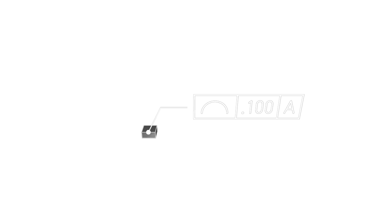
Profile Line
Profile Line controls how far selected edge geometry may deviate from its ideal two-dimensional profile. Use it for cross-sections, outlines, curved edges, and contour boundaries that need a tolerance zone following the intended shape.
Edges
Select one or more edges to control. Profile Line applies to edge geometry, so choose the outline, curve, or section whose shape tolerance should travel with the model.
Tolerance
Set the allowed deviation from the ideal profile in the current unit system.
Datums
Add datum references when the profile tolerance should be evaluated relative to a datum reference frame. Leave datums empty when the profile controls only form.
Precision
Choose how many decimal places to display in the annotation.
Frame Position
Place the feature control frame relative to the leader arrow. Move it far enough from the selected edge that the annotation stays readable.
Frame Plane
Choose the plane used to display the annotation frame. Use XY, XZ, or YZ when you need the
callout to face a predictable viewing direction.
Leader Scale
Adjust the visual size of the leader dot.
Font Size
Set the model-space height of the annotation text.
Are you interested in code?
Zoo Design Studio writes KCL behind the scenes. A Profile Line annotation uses gdt::profileLine
with one or more selected edges, a tolerance, and optional datum references.
Want to find out more about the gdt::profileLine function?
Check it out in our KCL docs.