Position
Position controls how far selected faces or edges may deviate from their intended location. Use it for holes, tabs, bosses, slots, and other features whose location matters relative to datums or neighboring geometry.
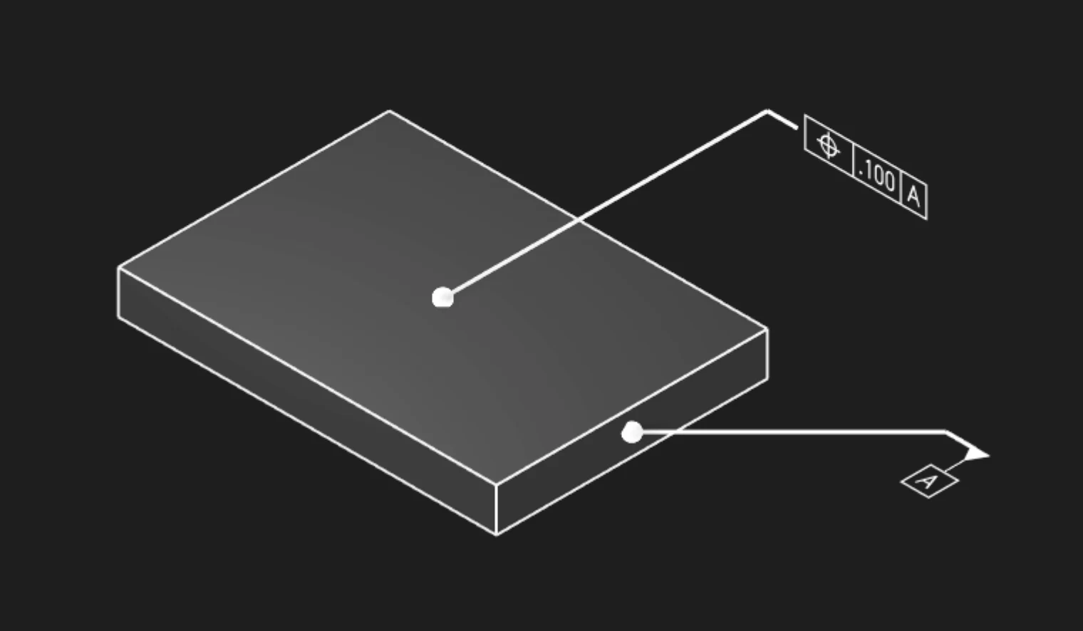
Faces Or Edges
Select the faces or edges whose location should be controlled. Faces are common for planar or cylindrical features, while edges are useful for profile boundaries and feature outlines.
Tolerance
Set the maximum positional variation allowed in the current unit system. The value is shown in the feature control frame.
Datums
Add datum references when the position tolerance should be evaluated against a datum reference frame. Position annotations commonly reference one or more datums.
Precision
Choose how many decimal places to display. Precision changes the visible annotation text only.
Frame Position
Place the feature control frame relative to the leader arrow. Keep the frame clear of dense model details so it remains readable.
Frame Plane
Choose the display plane for the feature control frame. Use the plane that keeps the annotation facing the viewer in your documentation or inspection workflow.
Leader Scale
Control the size of the leader dot that connects the annotation to the selected geometry.
Font Size
Set the model-space height of the annotation text.
Are you interested in code?
Zoo Design Studio writes KCL behind the scenes. A Position annotation uses gdt::position with
selected faces or edges, a tolerance, and optional datum references.
Want to find out more about the gdt::position function?
Check it out in our KCL docs.