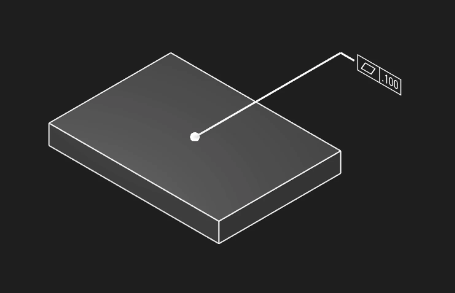
Flatness is a form control that constrains how much a surface may deviate from an ideal plane. Use Flatness annotations to specify tolerance zones for datum surfaces, sealing faces, mounting planes, and any feature requiring planar control without reference to external datums.
Options
Faces
Select the face or faces you want to control for flatness. Multiple faces can share the same tolerance if they form a common plane.
Tolerance
The maximum allowed deviation from a perfect plane, in your current units. This creates a tolerance zone between two parallel planes that the surface must fit within.
Typical values:
- 0.01-0.05mm - Precision sealing surfaces, gage blocks
- 0.05-0.1mm - High-precision mounting faces, machined datums
- 0.1-0.5mm - General machined surfaces, cast iron bases
- 0.5-2mm - Sheet metal, welded plates
Precision
How many decimal places to show in the annotation (affects display only, not the actual tolerance).
Frame Position
Where to place the tolerance callout box on the face, as [X, Y] coordinates.
Frame Plane
Which orientation to show the annotation:
- Standard planes (XY, YZ, XZ)
- Face-aligned
Leader Scale
Scale factor for the arrow connecting the callout to the surface. Increase this to make the annotation more visible.
Font Point Size
Font size in points for annotation text.
Font Scale
Overall scaling for all annotation elements.
GD&T Flatness Principles
Tolerance Zone Definition
The flatness tolerance zone consists of two parallel planes separated by the tolerance value. The surface must lie entirely within this zone, but the zone can be oriented at any angle. Flatness does not reference coordinate system orientation.
No Datum Reference
Flatness is a form control that does not reference datums. The tolerance zone can float to the optimal orientation that minimizes measured deviation. This differs from:
- Parallelism: Requires tolerance zone parallel to a datum
- Perpendicularity: Requires tolerance zone perpendicular to a datum
- Profile of a Surface: May reference datums and combine form, orientation, and location
Measurement and Verification
Flatness is typically measured using:
- Coordinate Measuring Machines (CMM): Probe multiple points, fit best-fit plane, calculate maximum deviation
- Dial indicators: Manual measurement over surface plate, restricts to one orientation
- Optical comparators: For precision parts, projects surface against optical flat
Design Applications
Datum Feature Surfaces
Define flatness for primary datum features that establish the datum reference frame:
- Machine tool tables and plates
- Gage mounting surfaces
- Assembly reference planes
Sealing and Mating Surfaces
Control flatness for reliable seal compression and load distribution:
- Hydraulic flange faces (gasket sealing)
- Electrical enclosure covers (EMI gasket seating)
- Pressure vessel closures
Precision Mechanisms
Ensure adequate flatness for low-friction sliding or precision motion:
- Linear guide mounting surfaces
- Optical bench plates
- Granite surface plates
Flatness vs Surface Roughness
Flatness (macro-geometry) and surface roughness (micro-geometry) are complementary but distinct:
- Flatness: Large-scale deviation over the full surface extent (mm to meters)
- Roughness: Small-scale surface texture (micrometers and smaller)
Both may be specified for critical surfaces. For example, a sealing surface might specify:
- Flatness: 0.05mm (macro planarity)
- Ra: 0.8 micrometers (micro surface finish)
Are you interested in code?
Zoo Design Studio writes KCL behind the scenes. A Flatness annotation uses gdt::flatness with
selected faces and a tolerance.
Want to find out more about the gdt::flatness function?
Check it out in our KCL docs.