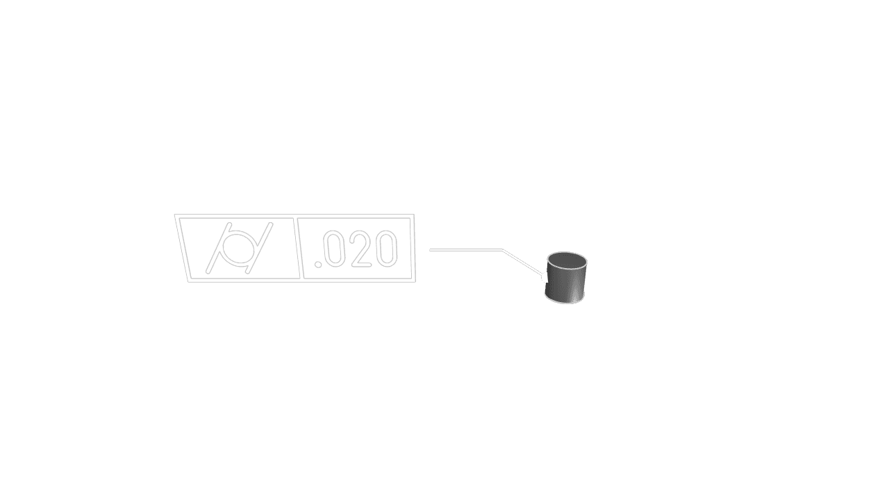
Cylindricity
Cylindricity controls how closely a cylindrical feature conforms to an ideal cylinder. Use it for shafts, pins, bores, sleeves, and turned surfaces where roundness, straightness, and taper need to be controlled together without referencing a datum.
Faces Or Edges
Select a cylindrical face when the whole surface must fit within the cylindrical tolerance zone. You can also select a circular edge when the requirement applies to a specific rim or section.
Tolerance
Set the allowed deviation from a perfect cylinder in the current unit system. The tolerance zone is between two coaxial cylinders whose radii differ by the tolerance value.
Precision
Choose how many decimal places to display for the tolerance value.
Frame Position
Place the feature control frame near the selected cylindrical feature while keeping it readable.
Frame Plane
Choose the display plane for the annotation. Use XY, XZ, or YZ to keep the frame facing the
intended view.
Leader Scale
Adjust the visual scale of the leader dot.
Font Size
Set the model-space height of the annotation text.
Are you interested in code?
Zoo Design Studio writes KCL behind the scenes. A Cylindricity annotation uses gdt::cylindricity
with selected faces or edges and a tolerance. Cylindricity is a form tolerance, so it does not use
datums.
Want to find out more about the gdt::cylindricity function?
Check it out in our KCL docs.