Perpendicularity
Perpendicularity controls how close selected faces or edges stay to a right-angle orientation from a datum or reference feature. Use it when a wall, bore, tab, or edge must remain square to a mating or inspection datum.
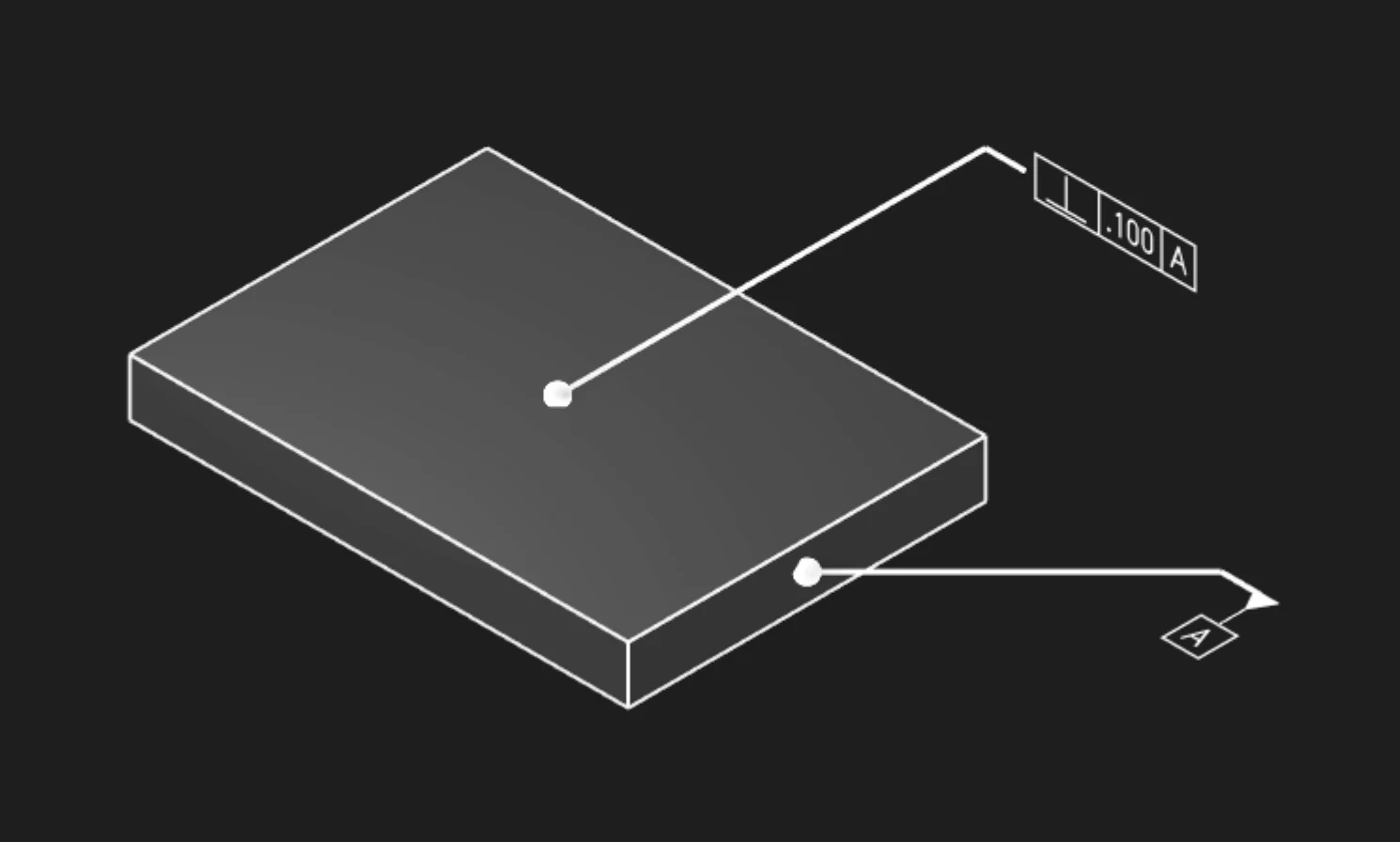
Faces Or Edges
Select the face or edge whose orientation should be controlled. Choose the geometry that directly represents the manufactured feature being inspected.
Tolerance
Set the allowed perpendicularity variation in the current unit system. The value defines the tolerance zone shown in the feature control frame.
Datums
Add the datum label or labels that define the reference orientation. Perpendicularity normally needs at least one datum to make the right-angle relationship meaningful.
Precision
Choose how many decimal places to display for the tolerance value.
Frame Position
Place the feature control frame near the controlled feature while keeping it clear of the model outline.
Frame Plane
Choose the display plane for the annotation. Use XY, XZ, or YZ to keep the frame legible in
the intended view.
Leader Scale
Adjust the visual scale of the leader dot.
Font Size
Set the model-space height of the annotation text.
Are you interested in code?
Zoo Design Studio writes KCL behind the scenes. A Perpendicularity annotation uses
gdt::perpendicularity with selected faces or edges, a tolerance, and datum references.
Want to find out more about the gdt::perpendicularity function?
Check it out in our KCL docs.