Extrude Solid
Use Extrude to pull a 2D sketch into 3D geometry perpendicular to or along its sketch plane. Extrude is one of the most fundamental solid modeling operations for creating base bodies, bosses, cuts, and pockets.
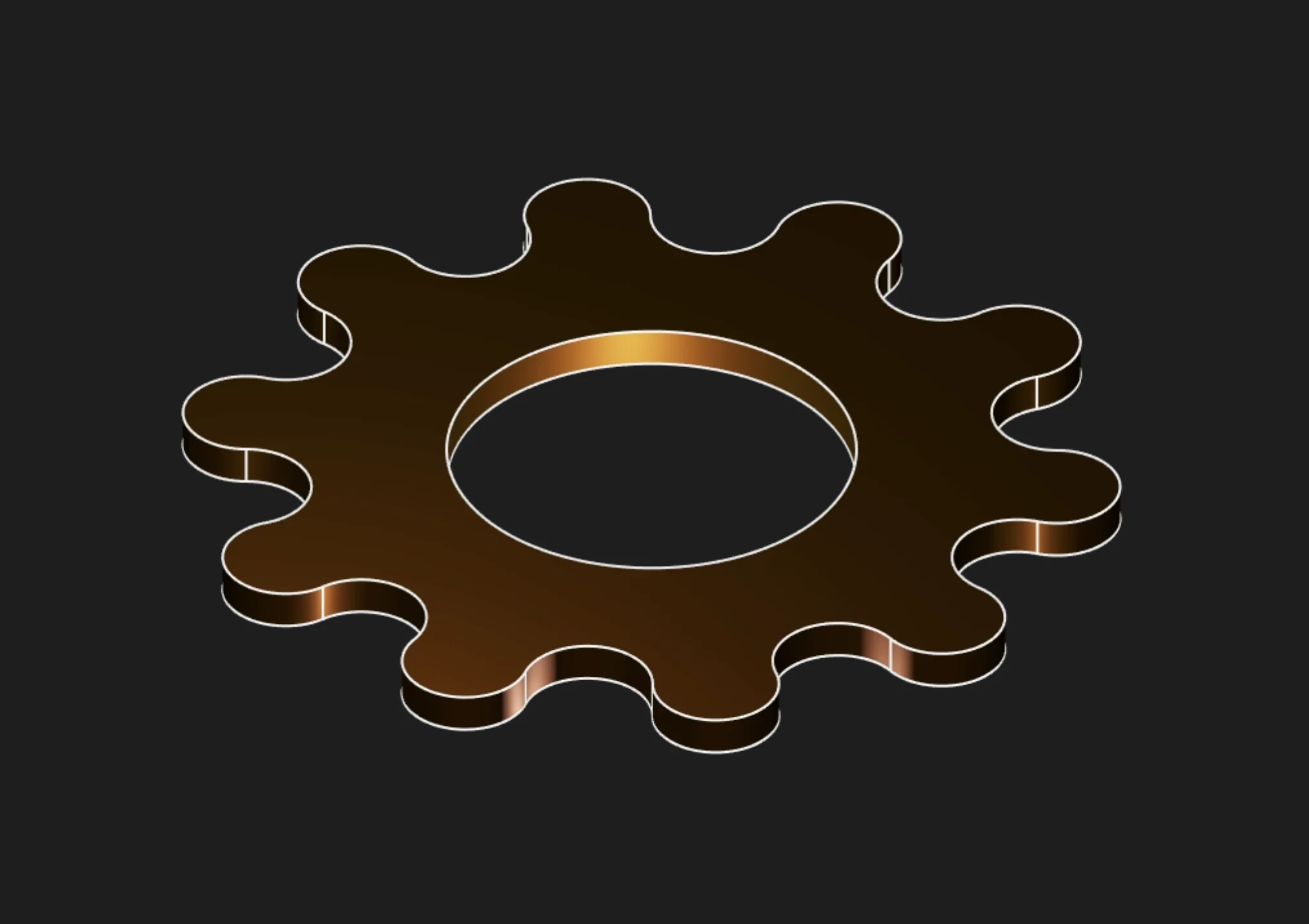
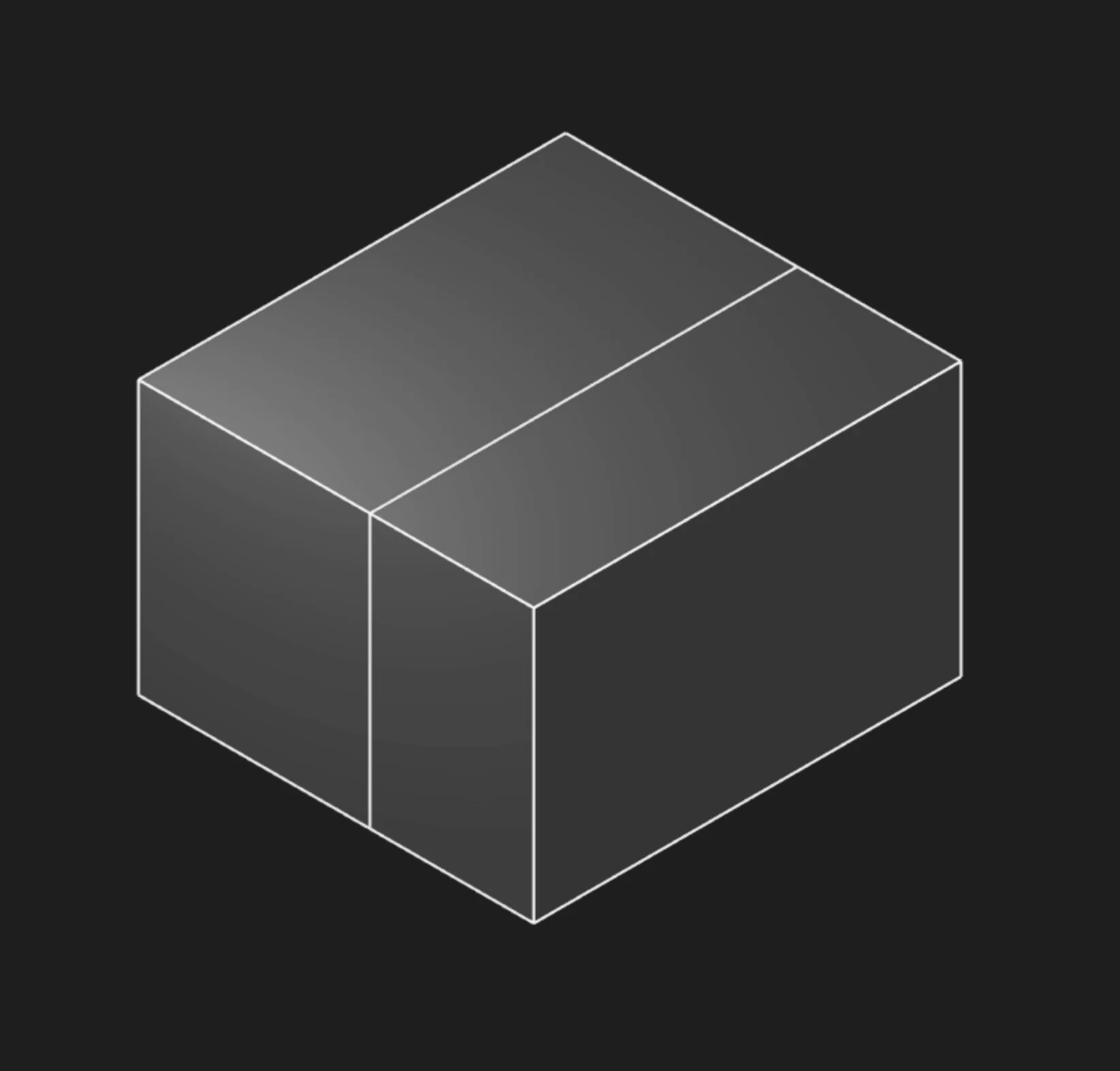
Extrude Solid pulls a selected sketch region into 3D
Sketches
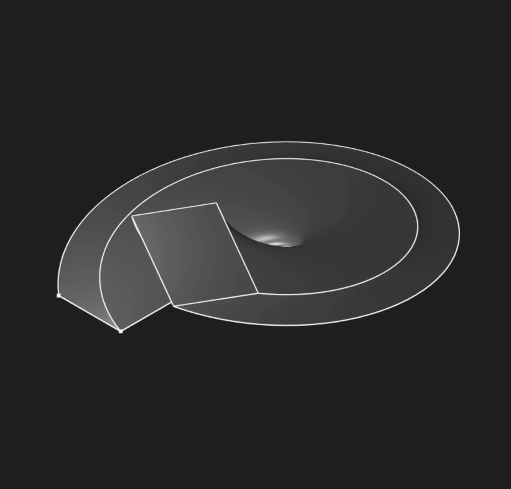
Select one or more sketch regions to extrude. A closed sketch encloses an area, and Zoo Design Studio exposes that filled area as a selectable region. For a solid extrude, select the region, not the individual sketch segments. Segments define the boundary, but the filled region is the profile that becomes the solid.
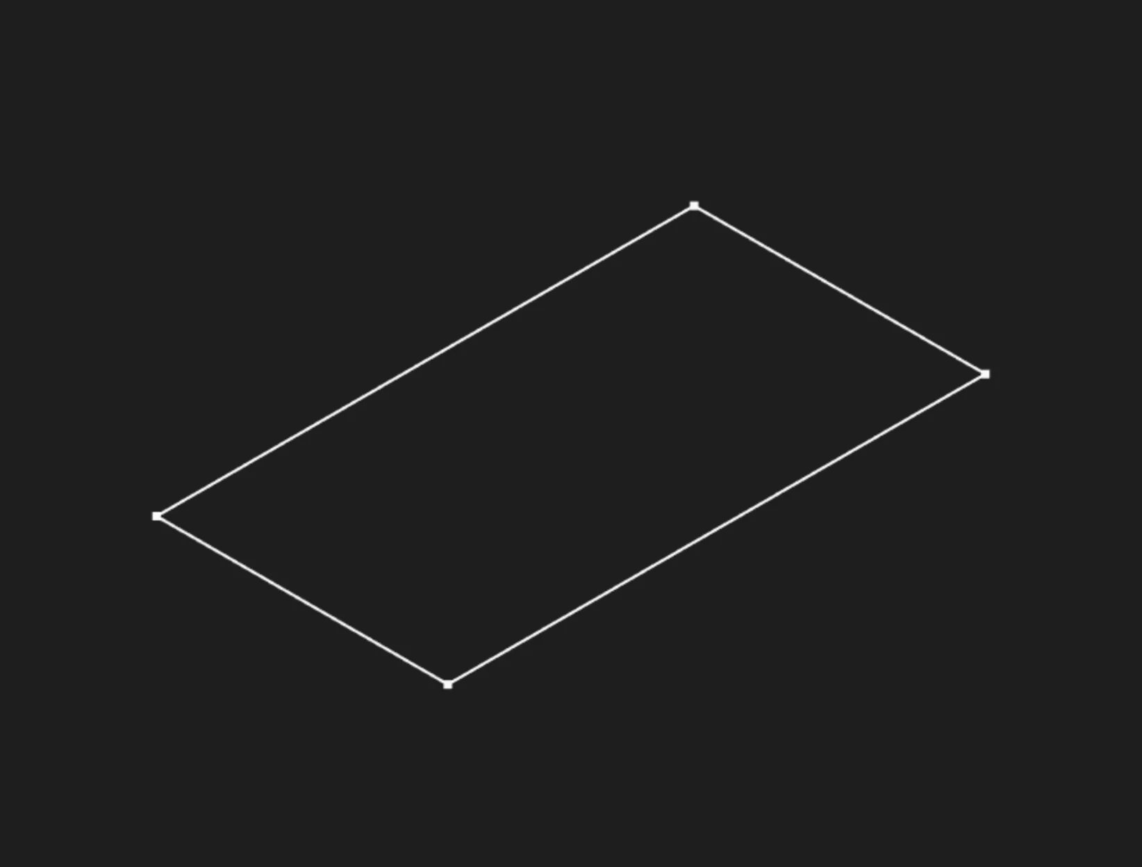
Sketch edges define the boundary, but the outline itself is not the solid profile selection
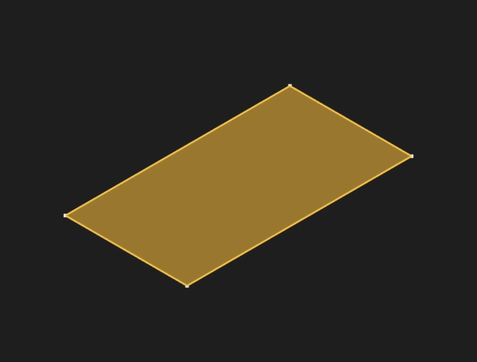
Select the filled sketch region to extrude it into a solid
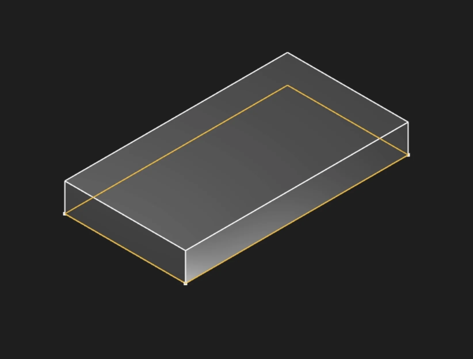
Length
Specify how far to extrude the sketch, measured perpendicular from the sketch plane. Enter the distance in your current unit system (mm, in, etc.).
Extrude To Face
Instead of specifying a fixed distance, select an existing face as the endpoint. The extrusion will automatically extend until it meets this face. Currently works with parallel faces only.
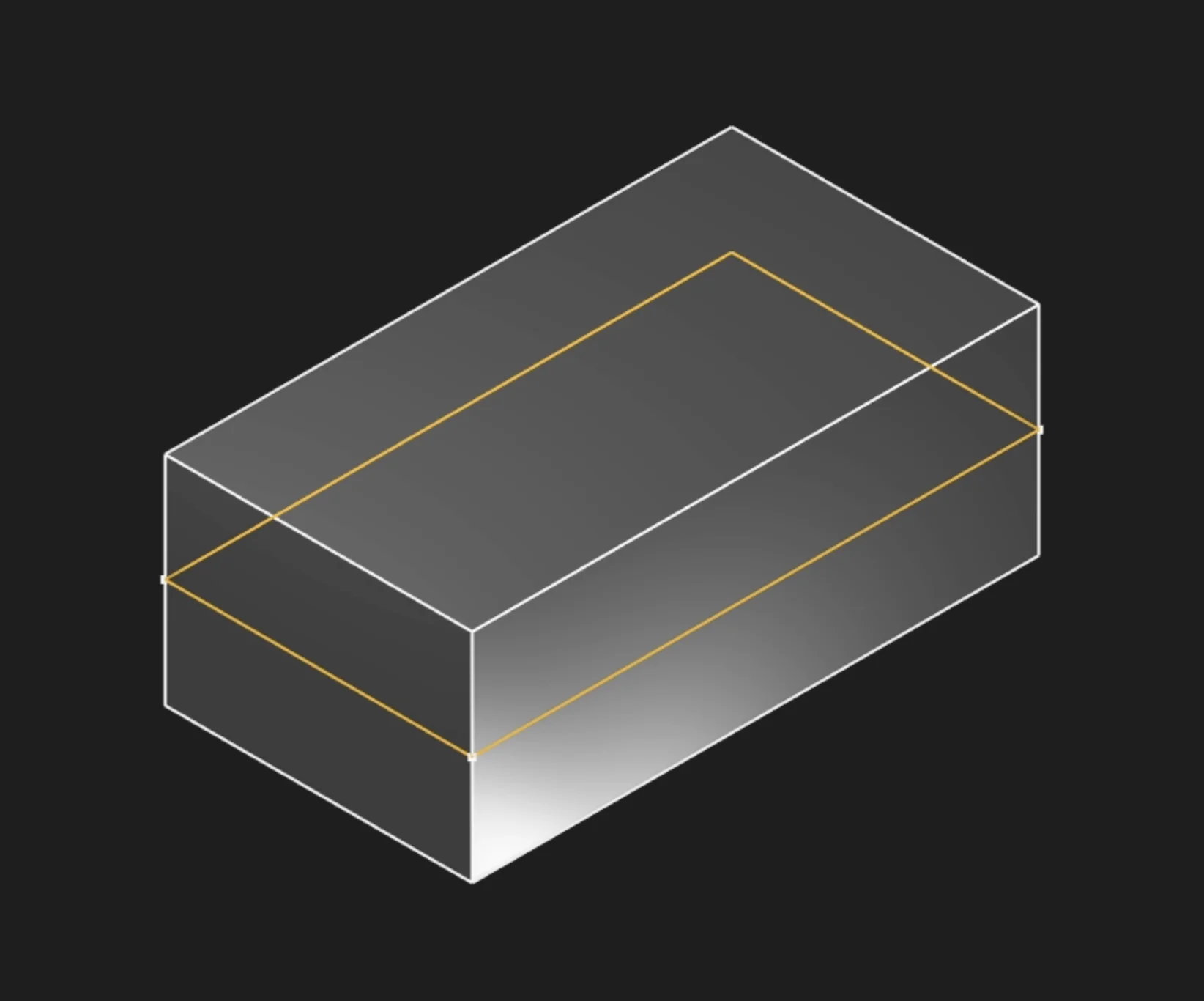
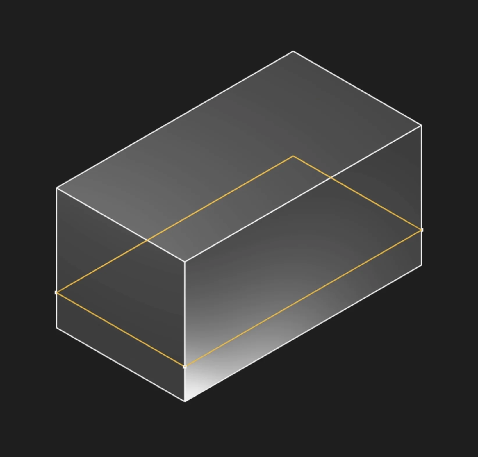
Symmetric
Enable this to extrude equally in both directions from the sketch plane. The total length gets split evenly: half goes forward, half goes backward. This keeps your feature centered on the sketch plane, which is useful when the sketch represents a critical centerline or datum.
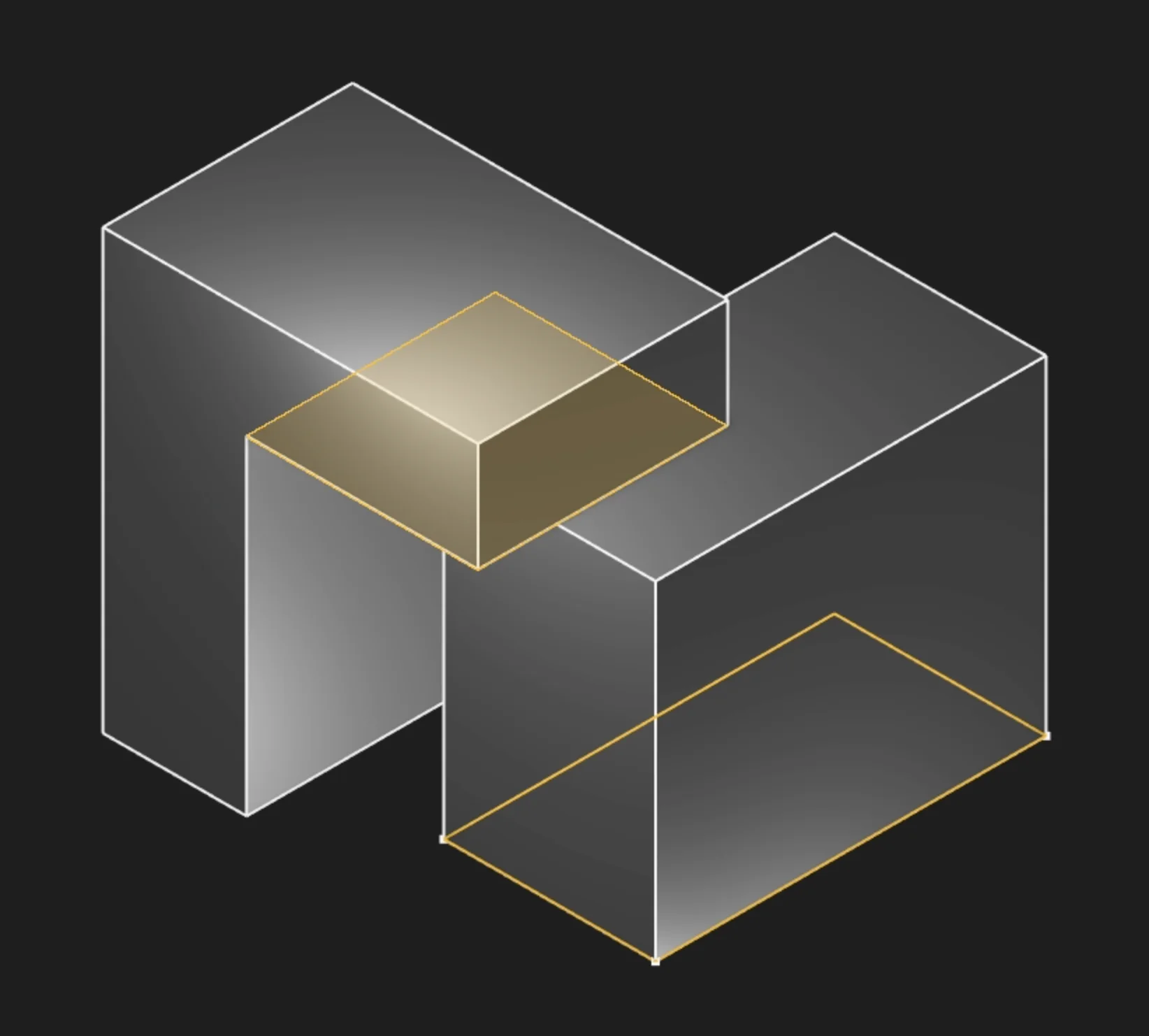
Bidirectional Length
When creating a non-symmetric bidirectional extrusion, this sets how far to extrude in the opposite direction from the main length.
In this example, the extrude uses two different lengths: 5mm in one direction and 2mm in the other. This allows you to create features that extend unequally from the sketch, giving you more control and flexibility for asymmetric or custom shapes.
Start Tag and End Tag
Apply tags to the start face (your original sketch plane) or end face (the extruded cap) to reference them in later operations. This is mainly used for referencing faces from other objects or features, especially in code or scripts. In the usual point-and-click UI flow, you don't need to set these tags. This is mostly for advanced users who want precise control or automation.
Twist Angle
Create a helical extrusion by specifying rotation in degrees. The profile rotates gradually from 0° at the start to your specified angle at the end, creating twisted geometry.
Twist Angle Step
Controls how smoothly the twist is calculated. Smaller steps create smoother twists but take longer to compute. Adjust this if you see faceting in your twisted extrusions.

Twist Center
Set the center point for the twist rotation using X,Y coordinates in the sketch plane. If you don't specify this, the twist rotates around the sketch origin.
Method
The method parameter controls how the extrusion interacts with existing geometry. There are two options: new and merge.
new: Always creates a new body, regardless of where you sketch. Use this for separate parts or when you don't want to join with existing geometry.
merge: Merges the extrusion with the body you sketched on. If you extrude in the positive direction, it adds material. If you extrude negatively, it cuts a hole (removes material) from the body.
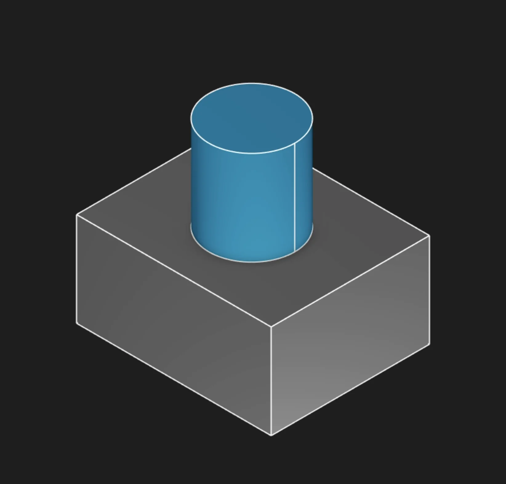
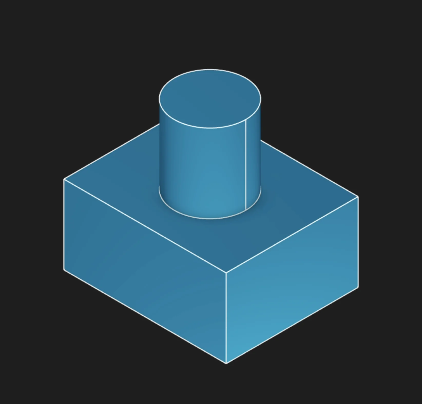
Hide Seams
This feature matters when you are extruding the faces of a solid, not just regions. It lets you control whether the edge lines (seams) between faces are visible on the resulting geometry.
Select a face to extrude

Hide Seams: On (default): no edge lines are shown between faces
Hide Seams: Off: edge lines are visible between faces
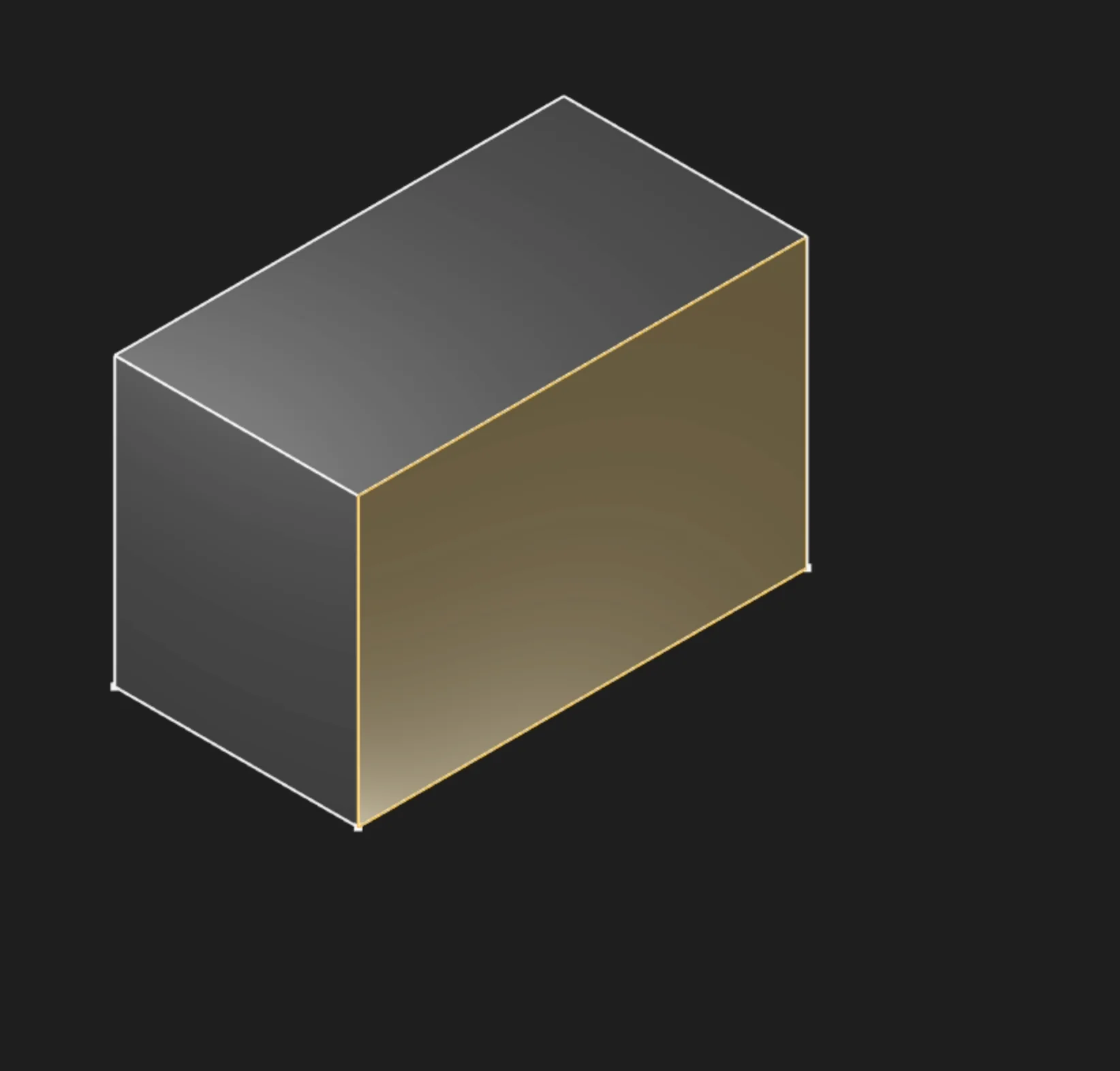
Body Type
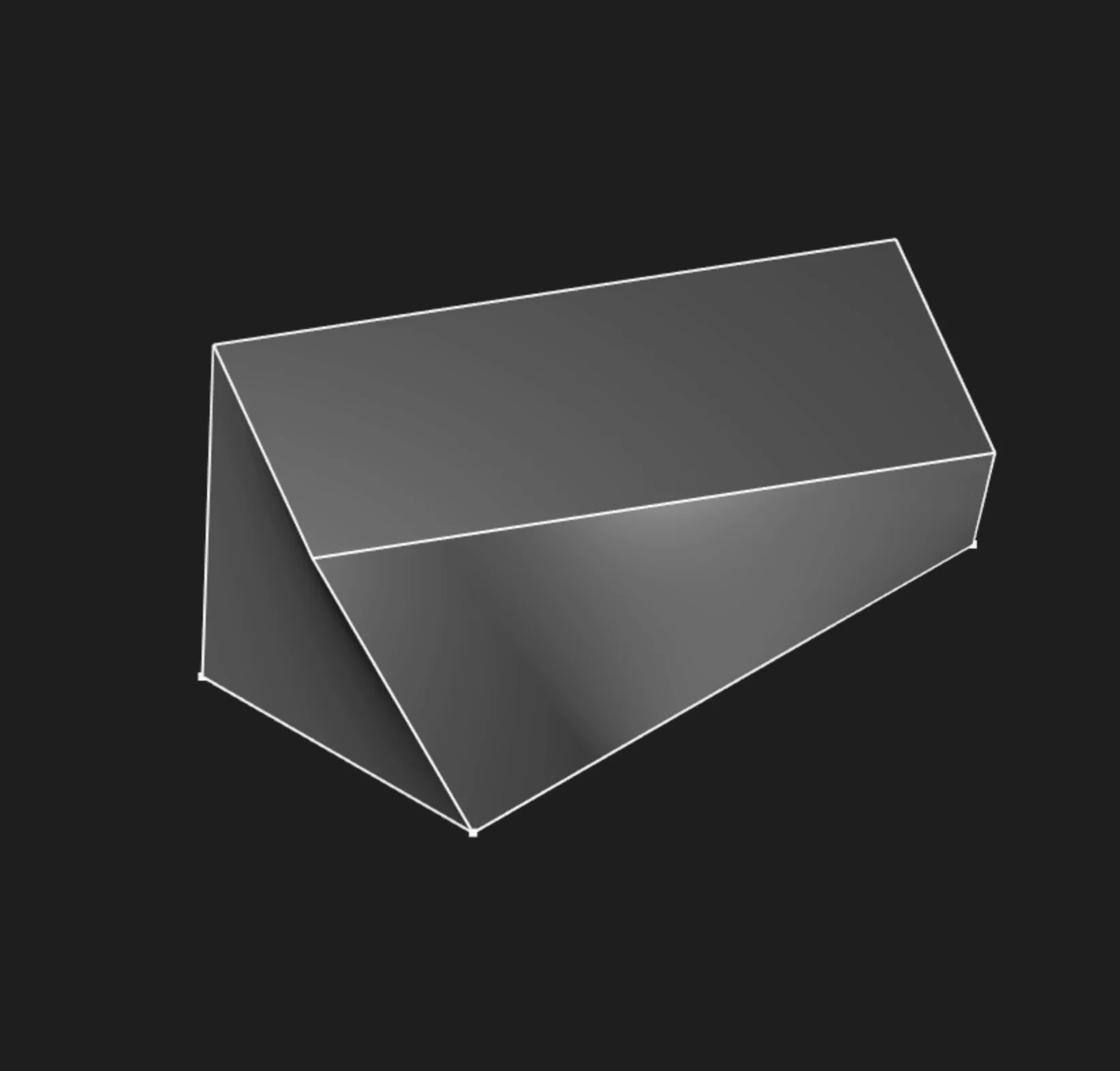
Choose whether to create a solid body (watertight volume) or a surface body (shell with no thickness). Most mechanical parts use solid body.
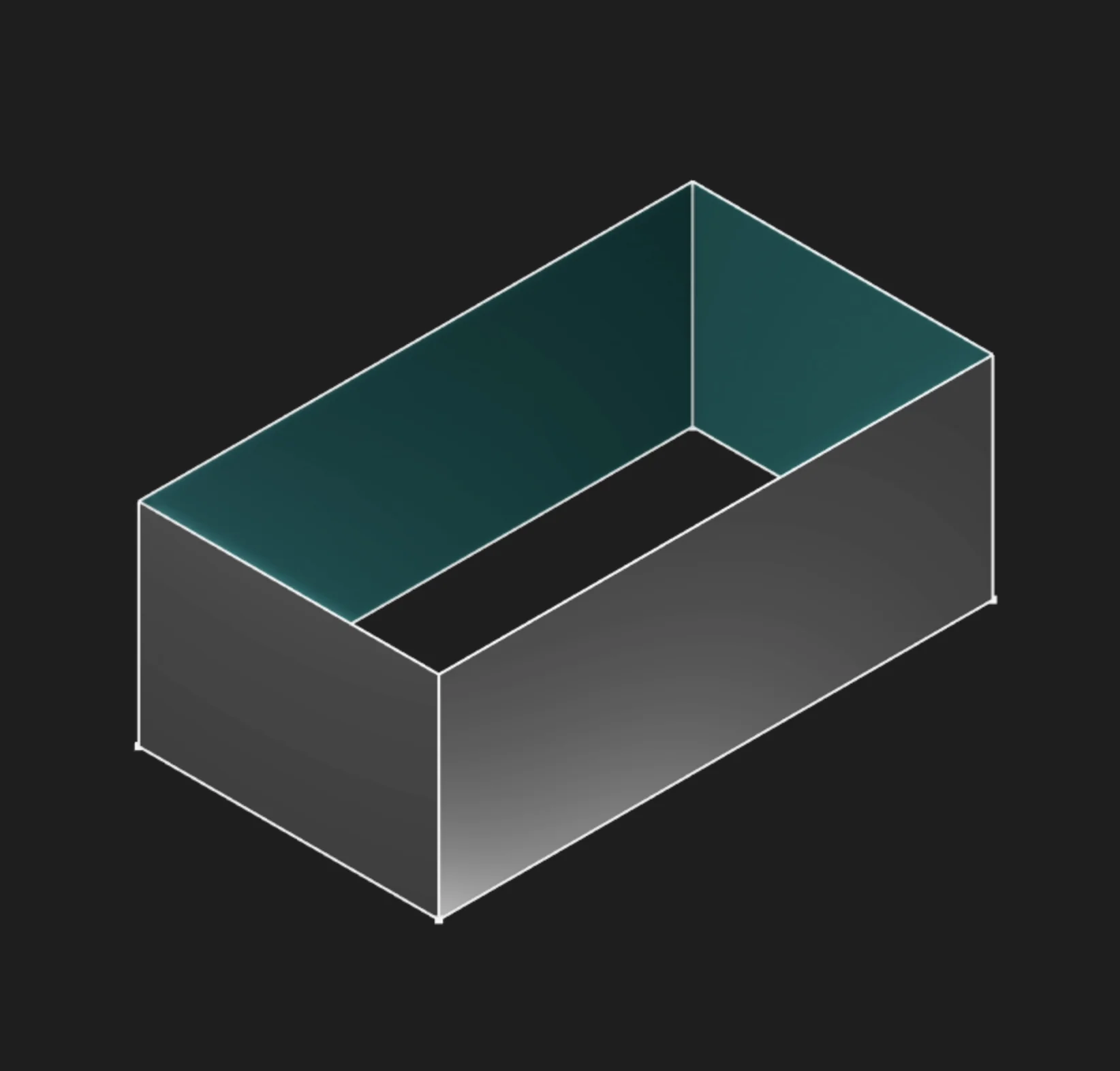
In this example, switching Body Type to Surface creates a hollow surface without the end caps.
If you want to learn more about surface modeling, see the Surface Extrude page.
Parameter Reference
sketches: The selected sketch profile or profiles. In the UI, select filled regions for solid
extrudes, not the boundary segments.
length: A fixed extrusion distance. Cannot be used at the same time as to.
to: A point, axis, plane, edge, face, sketch, solid, or tagged reference to extrude until. Cannot
be used with length or twistAngle.
symmetric: Splits the extrusion equally to both sides of the sketch plane.
bidirectionalLength: Adds a second extrusion distance in the opposite direction. Ignored when
symmetric is enabled.
tagStart: Names the start face at the original sketch plane for later reference.
tagEnd: Names the end face created by the extrusion for later reference.
twistAngle: Twists the profile as it extrudes. Cannot be used with to.
twistAngleStep: Controls the angular step used to calculate a twisted extrusion. Smaller values
are smoother but slower.
twistCenter: Sets the 2D center point of the twist relative to the sketch plane origin.
method: Chooses whether the extrusion creates a new body with NEW or merges with existing
geometry with MERGE.
hideSeams: Hides seams between the source face and merged result when extruding a face with
method = MERGE.
bodyType: Creates either a solid body or a surface body.
Prefer to learn by watching?
If you want to find out more in a different way, check out our video walkthrough:
Are you interested in code?
Zoo Design Studio writes KCL behind the scenes. Here’s an example of a solid extrude in KCL:
Want to find out more about the extrude function? Check it out in our KCL docs.