What's New With Zoo, October Edition
- Preview: Geometric Dimensioning and Tolerancing annotations
- UI for patterns
- Zoo MCP for AI integration
- Export to DXF (2D)
- Extrude _to_ (in KCL)
- Offsetting a chamfer
- And lots more
Hi, Zoo users! Another month has passed, and we're excited to share a lot of the updates we've made. We’ve been hard at work fixing bugs, improving performance and adding features since last time. Here are some of our favorites.
Preview: Geometric Dimensioning and Tolerancing annotations
We've added experimental support for annotating your CAD geometry with Geometric Dimensioning and Tolerancing (GD&T) labels. These help mechanical engineers explain the intent behind their designs, and share important requirements with their partners in testing, manufacturing etc.
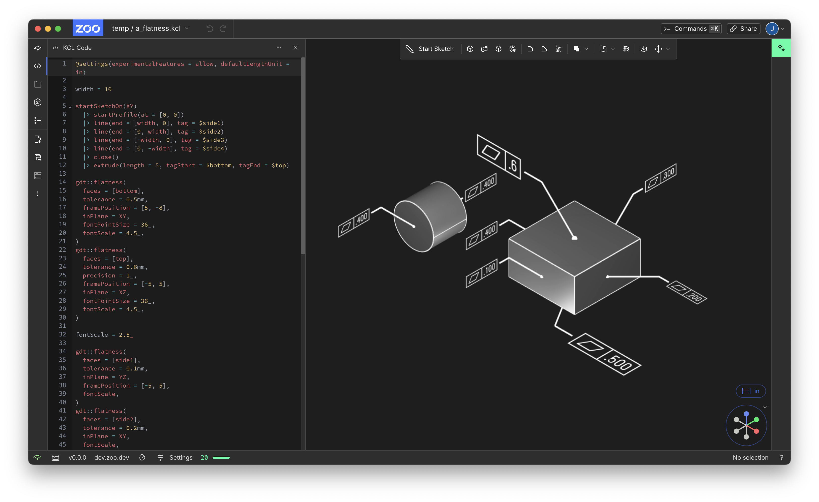
You'll need to enable experimental features by setting @settings(experimentalFeatures = allow) to use this preview. Note that this means we might change the KCL syntax for this feature, so if you enable it, be warned: a future update might break your old GD&T code.
This lets you call the gdt::flatness() function in KCL, which will add a beautiful little annotation to the model visuals. Here's an example program:
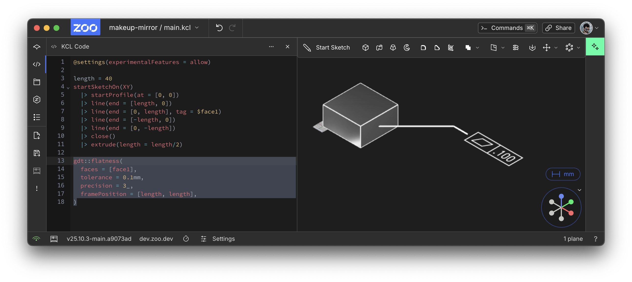
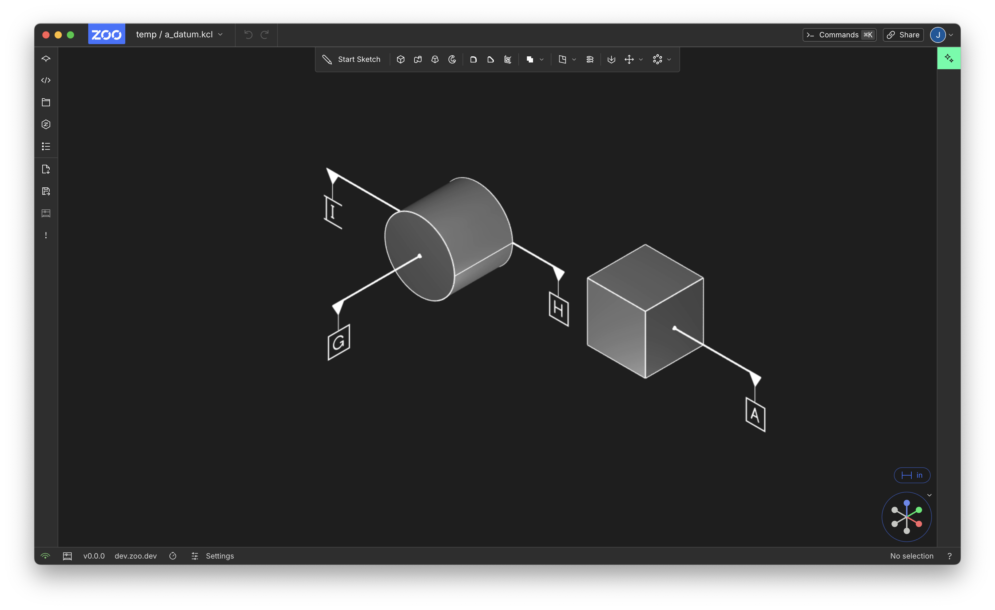
Because these annotations are stored in KCL, alongside the rest of your model, they'll be included whenever any other human or machine sends the file somewhere else, or reads it. Here's a preview of our next GD&T feature, general-purpose data with gdt::datum():
Congratulations to Jon for the frontend work (PR) and Mike for the beautiful graphics rendering in our engine!
We're excited to start building a whole host of GD&T features for Zoo that pass important design information through the whole lifecycle of your products, from design to manufacturing and beyond. See the docs page for more options for this annotation. We'll be adding more GD&T features soon, so keep checking back. If you want to give us feedback, or read about the future of GD&T in Zoo, you can read or comment here.
UI for patterns
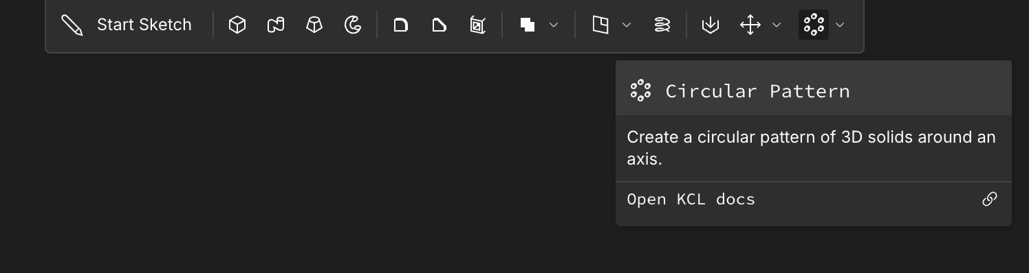
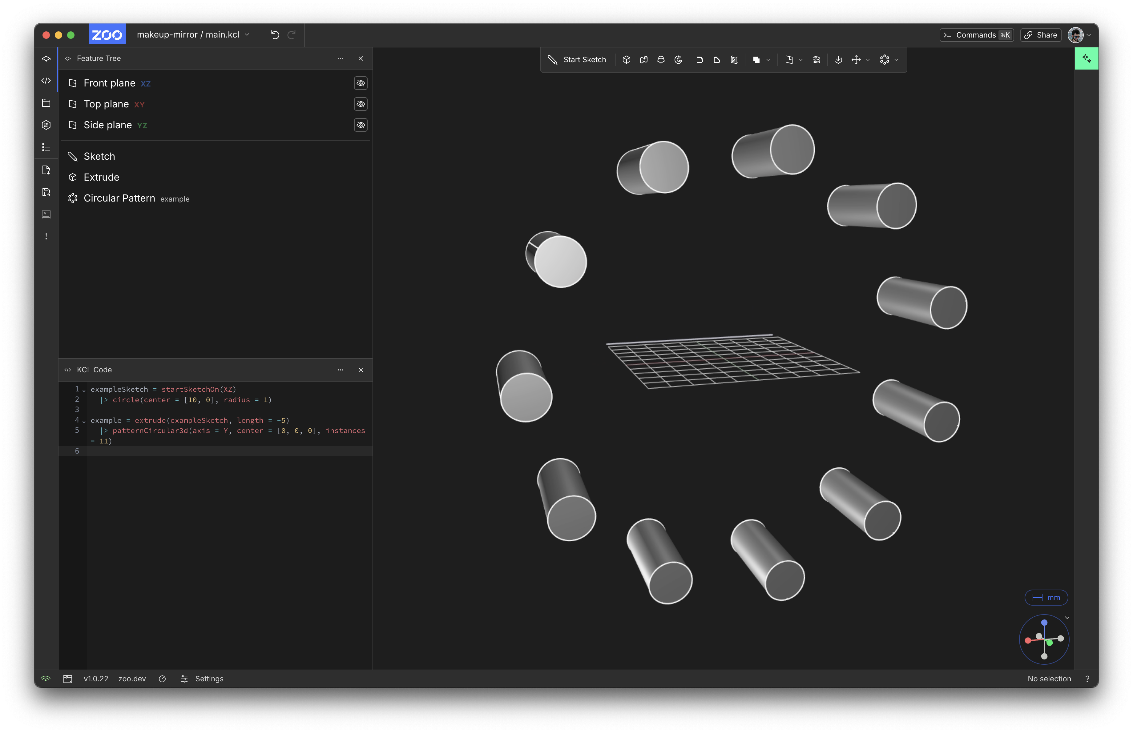
Patterns are critical for any serious mechanical engineer: rather than drawing the same screw hole 8 times, you draw it once, and use a pattern to create 8 copies. Zoo has supported this in KCL for a long time (see the KCL Book chapter on patterns), but there wasn't any button in the UI to activate it. Well, our excellent Maksym has added patterns to the UI! You can now press the circular pattern button:
And if you click the little arrow next to it, you can choose a linear pattern instead. Once you select a solid and pattern it, you'll see it repeated across the scene:
Maksym has demos of both circular and linear patterns at the linked PRs, and you can look at the circular or linear docs for more examples.
Zoo MCP for AI integration
Zoo Design Studio already has a powerful built-in AI modeling assistant, but we don't want to lock down our Text-to-CAD models -- we want them to be easy to integrate with other tools. So we've built an MCP server for Zoo. Right now, our MCP grants your AI tools two new capabilities: creating new CAD models, and editing existing ones. This is all powered by the same Text-to-CAD that's in Zoo Design Studio. It's fully open-source so we're excited to see what you build with it.
Export to DXF (2D)
Zoo is mostly used for 3D design, but it's also a fully-featured 2D design editor. This month we added support for exporting your sketches as 2D data in the DXF format (see PR). Just right-click a sketch in the Feature Tree and choose "Export to DXF". Here's a demo:
DXF is often used as a machine path for 2D tools, like CNC machines or laser cutters. So now you can do your 2D designs in Zoo, export them to DXF, then upload that to a laser cutter and cut out all sorts of things! If you use this, please let us know, we'd love to feature some of your work on our social media.
Big thanks to Katie for work on converting Zoo's data model to DXF, and Maksym for hooking it up to the app in this PR.
Extrude to (in KCL)
Extrude is one of the most important 3D operations in Zoo, and this month it became a lot more useful. Previously you had to know the exact distance you wanted to extrude, e.g. 3cm. But what if you want to extrude all the way to some other object, or plane? You'd need to calculate the distance yourself: take the shape you want to extrude, measure its distance to the destination, and then extrude that far.
For example, in this KCL, we model a cube, and then model a cylinder that should reach up to the cube.
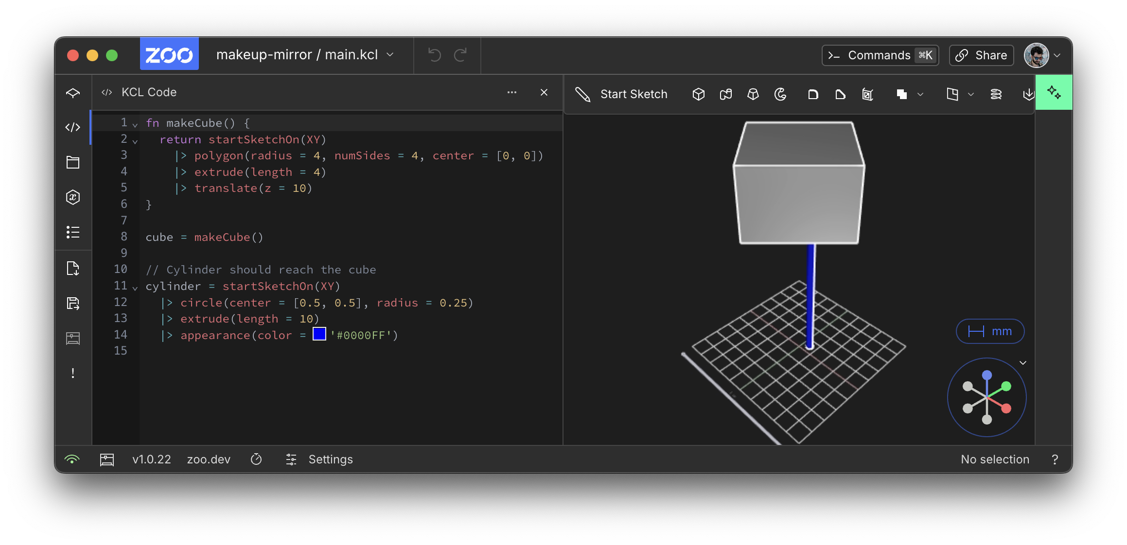
In this example, we know the cylinder's height has to be 10 because we can figure out where it'll meet the cube. The cube has been translated up 10mm high, so our cylinder has to do the same. But what if we can't read the makeCube function? What if the cube's position is really complicated to calculate? You might need to do a lot of manual math to figure out how far the extrusion should go. And that's a bad user experience. After all, Zoo Design Studio already knows where all the shapes are. Why can't I just say "make the cylinder as tall as you must in order to reach the cube?"
Well, now you can! KCL's extrude function now supports a new argument to. This lets you say "extrude the shape until it hits this target." Your target can be a plane, a point, another solid, etc. So now our extrude could be rewritten as:
This should simplify a lot of complex KCL models. Our mechanical engineers and customers have been asking for this for a while, and we're glad it's finally shipped. See the Extrude docs for more examples. Congratulations to Serena and Ben for shipping this (see the PR)! We're hard at work bringing this to the normal point-and-click mode, so that you don't need to open up the KCL panel to use it. That PR should be merged soon.
Offsetting a chamfer
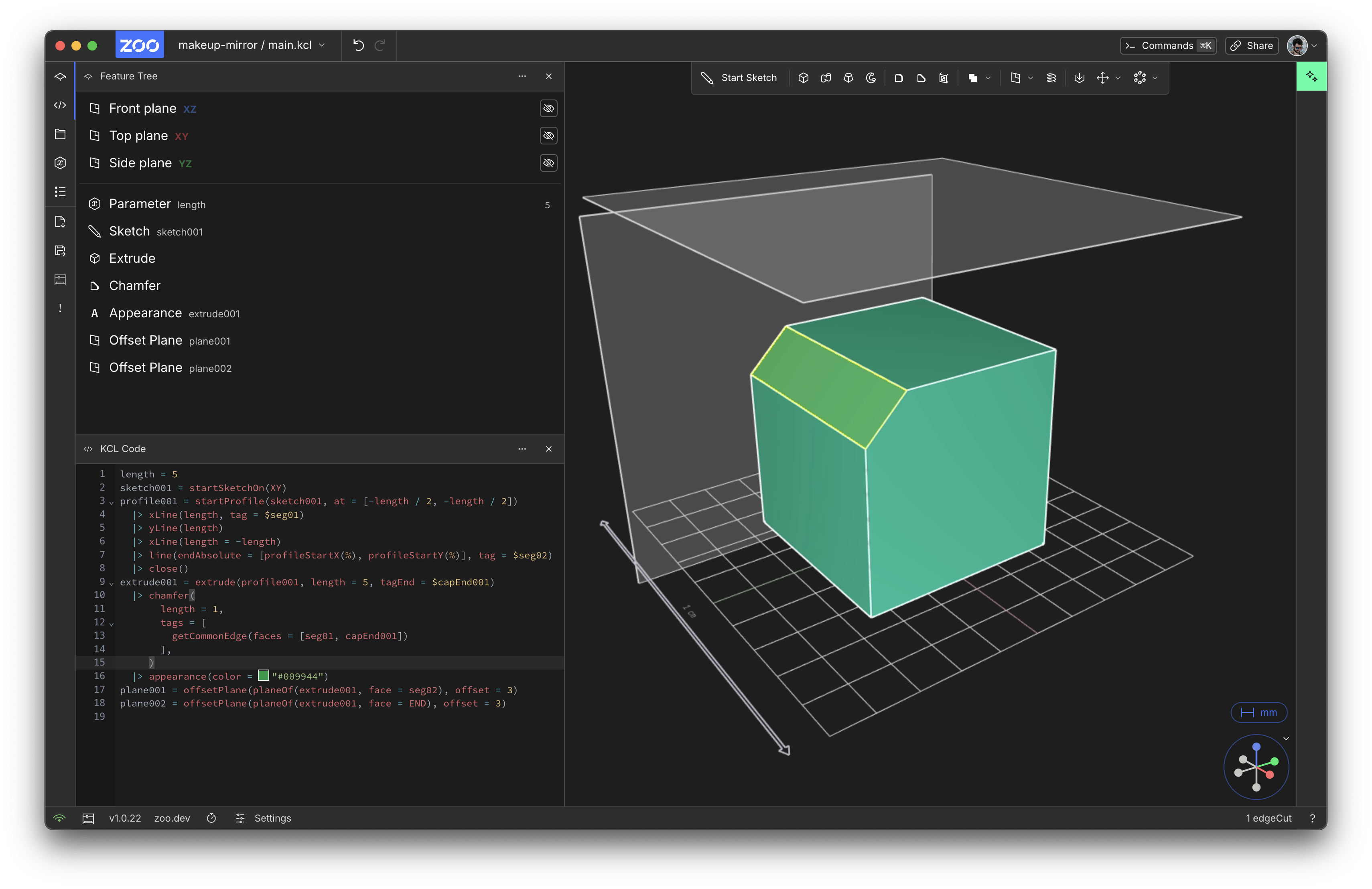
If you select a solid's face, you can click the Offset Plane button to create a new plane based on that face. This worked for almost all faces of your solids, but until recently it had a gap: faces from a chamfer couldn't be offset. In this example, you can see we've offset the cube's top and side faces, but not for the chamfered edge (selected in yellow).
Well, thanks to Pierre's PR this Just Works now!
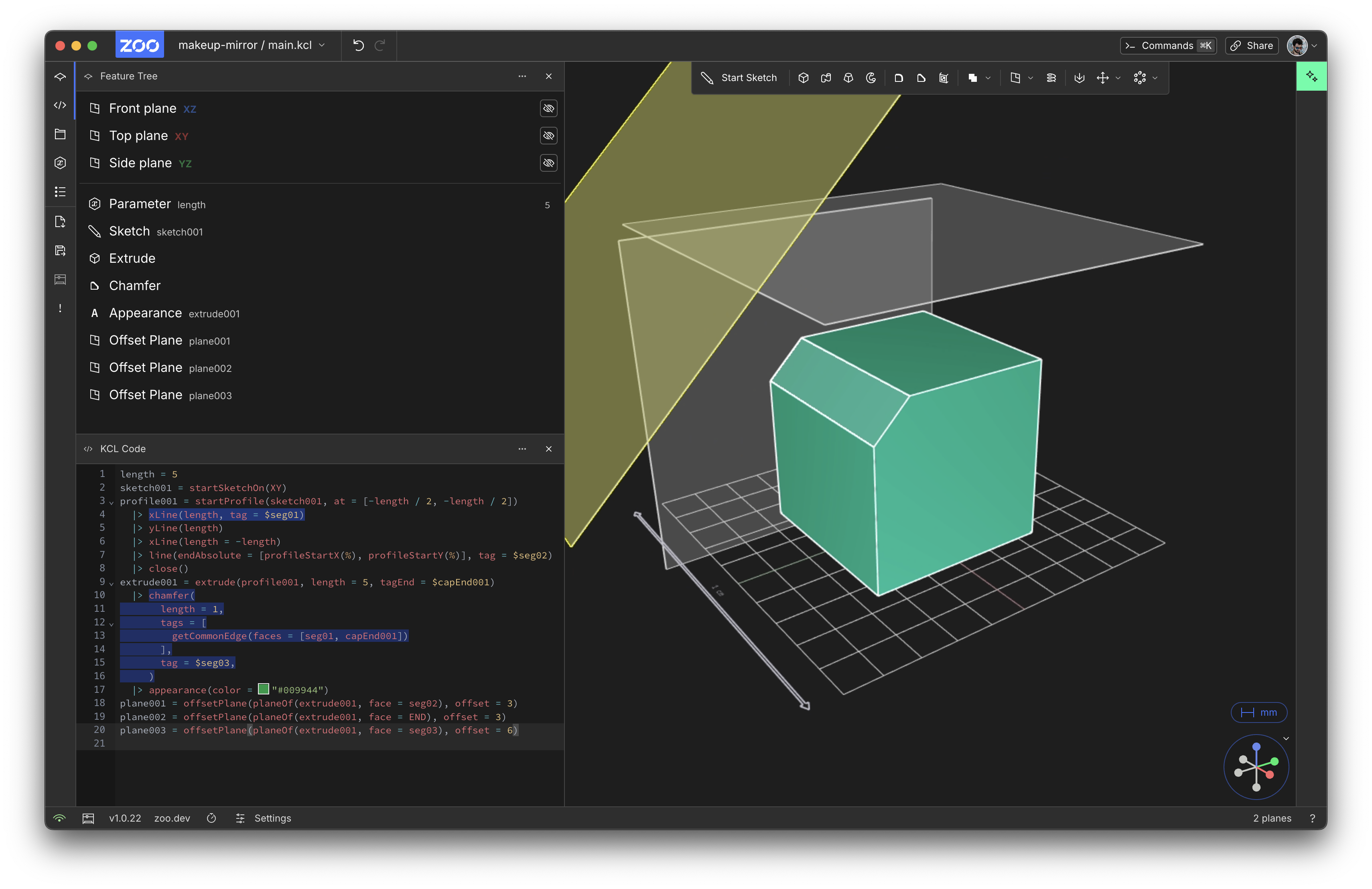
Here's a tiny video demo:
And lots more
We shipped a bunch of small improvements:
- Pressing "delete" on your keyboard now deletes the selected 2D profile
- Fixing visual distortions when you open and close and reopen panels
- Tags getting removed from your models
- Getting stuck in the three-point arc sketch tool
- Sketch tools getting unequipped when the KCL files changed on disk
- A better login menu for enterprise environments
- Subtracting solids from each other works in more cases (including one very nasty crash that would end your video stream)
Thanks for using Zoo! I really love writing these monthly updates and showing everyone all the improvements they get with our free updates. See you next month!
