Modeling 3D shapes
Previous chapters covered designing 2D shapes. Now it's time to design 3D shapes!
3D shapes are usually made by adding depth to a 2D shape. There are two common ways engineers do this: by extruding or revolving 2D shapes into 3D. There's some less common ways too, including sweeps and lofts. In this chapter, we'll go through each of these! Let's get started with the most common method: extruding.
Regions and Extrudes
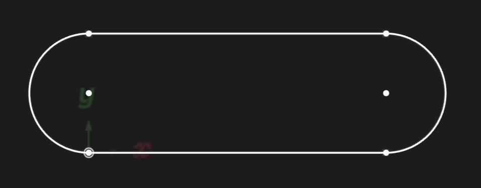
Extruding basically takes a 2D shape and pulls it up, stretching it upwards into the third dimension. Let's start with our existing 2D pill shape from the previous chapter:
height = 4
width = 10
pill = sketch(on = XY) {
  bot = line(start = [0, 0], end = [width, 0])
  top = line(start = [0, height], end = [width, height])
  left = arc(start = [0, height], end = [0, 0], center = [0, height/2])
  right = arc(start = [width, 0], end = [width, height], center = [width, height/2])
}
It should look like this:
Now we're going to extrude it up into the third axis, making a 3D solid.
pill = sketch(on = XZ) {
  line1 = line(start = [var -4.18mm, var 5.88mm], end = [var 1.34mm, var 5.85mm])
  line2 = line(start = [var 1.32mm, var 4.12mm], end = [var -4.19mm, var 4.15mm])
  arc1 = arc(start = [var -4.18mm, var 5.88mm], end = [var -4.19mm, var 4.15mm], center = [var -4.18mm, var 5.01mm])
  arc2 = arc(start = [var 1.32mm, var 4.12mm], end = [var 1.34mm, var 5.85mm], center = [var 1.33mm, var 4.99mm])
  coincident([arc1.start, line1.start])
  coincident([line1.end, arc2.end])
  coincident([arc2.start, line2.start])
  coincident([line2.end, arc1.end])
  parallel([line1, line2])
  equalLength([line1, line2])
  equalRadius([arc2, arc1])
  tangent([line1, arc1])
  tangent([line1, arc2])
}

// Add these lines!
region001 = region(point = pill.arc1.center, sketch = pill)
extrude001 = extrude(region001, length = 1)
You should see something like this:
NOTE: If you're reading this book online, the above graphic should be an interactive 3D model. You can use your mouse (or touchpad) to spin the model, zoom in and out, pan around the 3D scene, etc.
We added two different functions to our program: region and extrude. They work together: region lets you pick out a closed region of 2D space from your sketch, and extrude transforms that region into a 3D solid.
We need region because a sketch can contain lots of geometry. In the previous chapters, we used calls to line and arc to create closed shapes, like rhombuses and pills. But a sketch could contain multiple shapes, or free-floating lines that aren't part of any closed shape at all. Here's an example sketch:
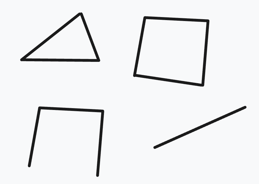
This sketch contains two closed shapes (a triangle and a square) as well as other lines. So, when we use the extrude function, we have to say which closed region we want to extrude. The region call takes in a point as its first parameter, and it returns the region that contains this point. If the point isn't actually in a closed region (in other words, if it's not surrounded by lines), the region call will return an error message.
You can pass either a named point, like point = pill.arc1.center, or a point literal (a 2D position, like point = [-1.44mm, 5.86mm]). We suggest you prefer named points over literal points, because if you edit your sketch, the exact boundaries of the geometry might change, and your target region might no longer enclose the specific position in your point literal!
NOTE: We're working on other ways to select regions, by choosing the lines (or arcs) that bound the region instead. We'll update this book when that API is ready.
Once you have a region of 2D space, you can turn that 2D space into 3D. We use the extrude function to take a region and say, "extrude it up into the 3rd dimension". extrude takes a distance, which is how far along the third axis to extrude. Every plane has a normal, or an axis which is tangent to the plane. For the plane XZ, this is the Y axis. This normal (also called the tangent, or the axis perpendicular to the plane), is the direction that extrude uses to add depth to your 2D region, making it 3D.
Advanced extrude options
bidirectionalLength = <number>: In addition to extruding up bylength, also extrude down by this much.symmetric = true: Instead of extruding up bylength, extrude up half the length, and down half the length. So, if you sketch onXYand thenextrude(length = 10), it'll extrude 10 fromZ=0toZ=10. But if you useextrude(length = 10, symmetric = true)it'll go fromZ=-5toZ=5.to = <target>: Set a target (you can use a point, axis, plane, edge, face, sketch or solid), and this will extrude until it makes the solid reach the target (or as close as it can possibly get).twistAngle = 30deg: While extruding, twist the sketch around its center. Or choose some other point to twist around, viatwistCenter. Change the twist speed withtwistAngleStep.
Sweep
An extrude takes some 2D region and drags it up in a straight line along the normal axis. A sweep is like an extrude, but the shape isn't just moved along a straight line: it could be moved along any path. Let's reuse our previous pill-shape example, but this time we'll sweep it instead of extruding it. First, we have to define a path that the sweep will take. Let's add one:
pillSketch = sketch(on = YZ) {
  line1 = line(start = [var -4.18mm, var 5.88mm], end = [var 1.34mm, var 5.85mm])
  line2 = line(start = [var 1.32mm, var 4.12mm], end = [var -4.19mm, var 4.15mm])
  arc1 = arc(start = [var -4.18mm, var 5.88mm], end = [var -4.19mm, var 4.15mm], center = [var -4.18mm, var 5.01mm])
  arc2 = arc(start = [var 1.32mm, var 4.12mm], end = [var 1.34mm, var 5.85mm], center = [var 1.33mm, var 4.99mm])
  coincident([arc1.start, line1.start])
  coincident([line1.end, arc2.end])
  coincident([arc2.start, line2.start])
  coincident([line2.end, arc1.end])
  parallel([line1, line2])
  equalLength([line1, line2])
  equalRadius([arc2, arc1])
  tangent([line1, arc1])
  tangent([line1, arc2])
}
pillRegion = region(point = [-1.44mm, 5.86mm], sketch = pillSketch)

pathSketch = sketch(on = XZ) {
  line1 = line(start = [var 0mm, var 5.06mm], end = [var -5.02mm, var 4.93mm])
  vertical([line1.start, ORIGIN])
  arc1 = arc(start = [var -4.54mm, var 12.82mm], end = [var -5.02mm, var 4.93mm], center = [var -5.12mm, var 8.9mm])
  coincident([line1.end, arc1.end])
  tangent([line1, arc1])
}

Our variable pathSketch has two lines (one straight line, one arc). Note that they don't form a region! They form an open profile, i.e. a sequence of lines that doesn't close back in on itself.
Now we'll add the sweep call, like sweep(pillRegion, path = [pathSketch.line1, pathSketch.arc1]), which will drag our 2D pill sketch along the path we defined. We'll add it to the bottom of our code:
// This is the same in the previous example program:
pillSketch = sketch(on = YZ) {
  line1 = line(start = [var -4.18mm, var 5.88mm], end = [var 1.34mm, var 5.85mm])
  line2 = line(start = [var 1.32mm, var 4.12mm], end = [var -4.19mm, var 4.15mm])
  arc1 = arc(start = [var -4.18mm, var 5.88mm], end = [var -4.19mm, var 4.15mm], center = [var -4.18mm, var 5.01mm])
  arc2 = arc(start = [var 1.32mm, var 4.12mm], end = [var 1.34mm, var 5.85mm], center = [var 1.33mm, var 4.99mm])
  coincident([arc1.start, line1.start])
  coincident([line1.end, arc2.end])
  coincident([arc2.start, line2.start])
  coincident([line2.end, arc1.end])
  parallel([line1, line2])
  equalLength([line1, line2])
  equalRadius([arc2, arc1])
  tangent([line1, arc1])
  tangent([line1, arc2])
}
pillRegion = region(point = [-1.44mm, 5.86mm], sketch = pillSketch)

pathSketch = sketch(on = XZ) {
  line1 = line(start = [var 0mm, var 5.06mm], end = [var -5.02mm, var 4.93mm])
  vertical([line1.start, ORIGIN])
  arc1 = arc(start = [var -4.54mm, var 12.82mm], end = [var -5.02mm, var 4.93mm], center = [var -5.12mm, var 8.9mm])
  coincident([line1.end, arc1.end])
  tangent([line1, arc1])
}

// Add this new line of code to your program!
// Sweep the pill-shaped region along the given path.
sweep(pillRegion, path = [pathSketch.line1, pathSketch.arc1])
Advanced sweep options
The sweep call has several other options you can set, listed in its documentation. Here are some optional parameters you can use to tweak the exact algorithm Zoo uses to compute the sweep:
relativeTo = sweep::TRAJECTORYorrelativeTo = sweep::SKETCH_PLANEaffects how the shape being swept will move along the path. This is optional and defaults tosweep::TRAJECTORY.version = 1orversion = 2will change which Zoo sweep algorithm to use. The default, 0, means the Zoo engine will use whichever it thinks is best. 1 is the version we first launched Zoo with, and 2 is a new improved version that works better in many cases.sectional = truewill divide the swept path into several different stages, one per line in the path. The default issectional = false.
If your sweep looks strange, try playing around with these options, or read the sweep docs page for more information.
Revolve
Revolves are another common way to make a 3D shape. Let's start with a 2D shape, like a basic circle.
circleSketch = sketch(on = XZ) {
  // Sketch a circle whose center is [20, 0].
  circle1 = circle(start = [var 0mm, var 1mm], center = [var 0mm, var 0mm])
  fixed([circle1.center, [20, 0]])

  // Use construction geometry to set the circle's radius to 1mm.
  vertical([circle1.start, circle1.center])
  line1 = line(start = [var 0mm, var 0mm], end = [var 0mm, var 1mm], construction = true)
  coincident([line1.start, circle1.center])
  coincident([line1.end, circle1.start])
  distance([line1.start, line1.end]) == 1mm
}

Note that we placed the circle at [20, 0], i.e. 20 units away from the global origin.
The revolve function takes a shape and revolves it, by dragging it around an axis. Let's revolve our circle around the Y axis (which is perpendicular to XZ, the plane we're sketching on), to make a ring shape. Because the circle being revolved is 20 units away from the global origin, the ring produced by the revolve should have a radius of 20.
circleSketch = sketch(on = XZ) {
  // Sketch a circle whose center is [20, 0].
  circle1 = circle(start = [var 0mm, var 1mm], center = [var 0mm, var 0mm])
  fixed([circle1.center, [20, 0]])

  // Use construction geometry to set the circle's radius to 1mm.
  vertical([circle1.start, circle1.center])
  line1 = line(start = [var 0mm, var 0mm], end = [var 0mm, var 1mm], construction = true)
  coincident([line1.start, circle1.center])
  coincident([line1.end, circle1.start])
  distance([line1.start, line1.end]) == 1mm
}

// Pick the region inside the circle
region001 = region(point = [20mm, -0.9975mm], sketch = circleSketch)

// Revolve it around the center of the scene
revolve001 = revolve(region001, axis = Y)
revolve has an optional argument called angle. In the above example, we didn't provide it, so it defaulted to 360 degrees. But we can set it to 240 degrees, and get two thirds of a donut:
// This part is the same as the previous example:
circleSketch = sketch(on = XZ) {
  circle1 = circle(start = [var 0mm, var 1mm], center = [var 0mm, var 0mm])
  fixed([circle1.center, [20, 0]])
  vertical([circle1.start, circle1.center])
  line1 = line(start = [var 0mm, var 0mm], end = [var 0mm, var 1mm], construction = true)
  coincident([line1.start, circle1.center])
  coincident([line1.end, circle1.start])
  distance([line1.start, line1.end]) == 1mm
}
region001 = region(point = [20mm, -0.9975mm], sketch = circleSketch)

// Change the angle to 240deg
revolve001 = revolve(region001, angle = 240deg, axis = Y)
Spheres
You can make a sphere by revolving a semicircle its full 360 degrees. First, let's make a semicircle:
semiCircleSketch = sketch(on = XZ) {
  arc1 = arc(start = [var 1.81mm, var -2.03mm], end = [var -1.91mm, var 1.94mm], center = [var 0mm, var 0mm])
  coincident([arc1.center, ORIGIN])
  line1 = line(start = [var 0mm, var 1.74mm], end = [var 0mm, var 0mm])
  vertical([line1.start, ORIGIN])
  coincident([line1.end, arc1.center])
  line2 = line(start = [var 0mm, var 0mm], end = [var 0mm, var -1.92mm])
  coincident([line2.start, line1.end])
  vertical([line2.end, ORIGIN])
  equalLength([line1, line2])
  distance([line1.start, line1.end]) == 1.83mm
  coincident([line1.start, arc1.end])
  coincident([arc1.start, line2.end])
}

Then we can revolve that semicircle 360 degrees to make a sphere:
semiCircleSketch = sketch(on = XZ) {
  arc1 = arc(start = [var 1.81mm, var -2.03mm], end = [var -1.91mm, var 1.94mm], center = [var 0mm, var 0mm])
  coincident([arc1.center, ORIGIN])
  line1 = line(start = [var 0mm, var 1.74mm], end = [var 0mm, var 0mm])
  vertical([line1.start, ORIGIN])
  coincident([line1.end, arc1.center])
  line2 = line(start = [var 0mm, var 0mm], end = [var 0mm, var -1.92mm])
  coincident([line2.start, line1.end])
  vertical([line2.end, ORIGIN])
  equalLength([line1, line2])
  distance([line1.start, line1.end]) == 1.83mm
  coincident([line1.start, arc1.end])
  coincident([arc1.start, line2.end])
}

semiCircleRegion = region(point = [1.8275mm, 0mm], sketch = semiCircleSketch)
revolve001 = revolve(semiCircleRegion, axis = Y)

Note that here, we omitted the angle argument from the revolve call because it defaults to 360 degrees.
Lofts
All previous methods -- extrudes, sweeps, revolves -- took a single 2D shape and made a single 3D solid. Lofts are a little different -- they take multiple 2D shapes and join them to make a single 3D shape. A loft interpolates between various sketches, creating a volume that smoothly blends from one shape into another. Let's see an example:
// Sketch a square
square = sketch(on = XY) {
  line1 = line(start = [var 0mm, var -2mm], end = [var 2mm, var -2mm])
  line2 = line(start = [var 2mm, var -2mm], end = [var 2mm, var 0mm])
  line3 = line(start = [var 2mm, var 0mm], end = [var 0mm, var 0mm])
  line4 = line(start = [var 0mm, var 0mm], end = [var 0mm, var -2mm])
  coincident([line1.end, line2.start])
  coincident([line2.end, line3.start])
  coincident([line3.end, line4.start])
  coincident([line4.end, line1.start])
  parallel([line2, line4])
  parallel([line3, line1])
  perpendicular([line1, line2])
  horizontal(line3)
  equalLength([line1, line2, line3, line4])
  perpendicular([line4, line1])
  coincident([line4.start, [-5mm, 5mm]])
  distance([line3.start, line3.end]) == 10mm
}

// Sketch a circle, 10mm above the square.
circle = sketch(on = offsetPlane(XY, offset = 10mm)) {
  circle1 = circle(start = [var 0mm, var 1.5mm], center = [var 0mm, var 0mm])
  coincident([circle1.center, ORIGIN])
  vertical([circle1.start, circle1.center])
  distance([circle1.start, circle1.center]) == 1.5mm
}

// Pick out the right regions from each sketch.
squareRegion = region(point = [0mm, -4.9975mm], sketch = square)
circleRegion = region(point = [0mm, -1.4975mm], sketch = circle)

// Loft the square into the circle.
loft([squareRegion, circleRegion])
offsetPlane function to start the circle sketch above the XY plane. We'll cover offsetPlane more in the chapter on planes. The loft function has a few other advanced options you can set. One of these is vDegree, which affects how smoothly KCL interpolates between the shapes. Take a look at these two examples, which are identical except for vDegree. This example uses vDegree = 1:
// Sketch a square
square = sketch(on = XY) {
  line1 = line(start = [var 0mm, var -2mm], end = [var 2mm, var -2mm])
  line2 = line(start = [var 2mm, var -2mm], end = [var 2mm, var 0mm])
  line3 = line(start = [var 2mm, var 0mm], end = [var 0mm, var 0mm])
  line4 = line(start = [var 0mm, var 0mm], end = [var 0mm, var -2mm])
  coincident([line1.end, line2.start])
  coincident([line2.end, line3.start])
  coincident([line3.end, line4.start])
  coincident([line4.end, line1.start])
  parallel([line2, line4])
  parallel([line3, line1])
  perpendicular([line1, line2])
  horizontal(line3)
  equalLength([line1, line2, line3, line4])
  perpendicular([line4, line1])
  coincident([line4.start, [-5mm, 5mm]])
  distance([line3.start, line3.end]) == 10mm
}

// Sketch a circle, 10mm above the square.
circle = sketch(on = offsetPlane(XY, offset = 10mm)) {
  circle1 = circle(start = [var 0mm, var 1.5mm], center = [var 0mm, var 0mm])
  coincident([circle1.center, ORIGIN])
  vertical([circle1.start, circle1.center])
  distance([circle1.start, circle1.center]) == 1.5mm
}

// Another square, above the other shapes.
square2 = sketch(on = offsetPlane(XY, offset = 20mm)) {
  line1 = line(start = [var 0mm, var -2mm], end = [var 2mm, var -2mm])
  line2 = line(start = [var 2mm, var -2mm], end = [var 2mm, var 0mm])
  line3 = line(start = [var 2mm, var 0mm], end = [var 0mm, var 0mm])
  line4 = line(start = [var 0mm, var 0mm], end = [var 0mm, var -2mm])
  coincident([line1.end, line2.start])
  coincident([line2.end, line3.start])
  coincident([line3.end, line4.start])
  coincident([line4.end, line1.start])
  parallel([line2, line4])
  parallel([line3, line1])
  perpendicular([line1, line2])
  horizontal(line3)
  equalLength([line1, line2, line3, line4])
  perpendicular([line4, line1])
  coincident([line4.start, [-5mm, 5mm]])
  distance([line3.start, line3.end]) == 10mm
}

// Pick out the right regions from each sketch.
squareRegion = region(point = [0mm, -4.9975mm], sketch = square)
circleRegion = region(point = [0mm, -1.4975mm], sketch = circle)
squareRegion2 = region(point = [0mm, -4.9975mm], sketch = square2)

// Loft the square into the circle.
loftedSolid = loft([squareRegion, circleRegion, squareRegion2], vDegree = 1)
vDegree = 2. That's actually the default, so we don't need to set it, but for the sake of example we'll explicitly set it there.
Click here for the same KCL code, but using vDegree = 2
// Sketch a square
square = sketch(on = XY) {
  line1 = line(start = [var 0mm, var -2mm], end = [var 2mm, var -2mm])
  line2 = line(start = [var 2mm, var -2mm], end = [var 2mm, var 0mm])
  line3 = line(start = [var 2mm, var 0mm], end = [var 0mm, var 0mm])
  line4 = line(start = [var 0mm, var 0mm], end = [var 0mm, var -2mm])
  coincident([line1.end, line2.start])
  coincident([line2.end, line3.start])
  coincident([line3.end, line4.start])
  coincident([line4.end, line1.start])
  parallel([line2, line4])
  parallel([line3, line1])
  perpendicular([line1, line2])
  horizontal(line3)
  equalLength([line1, line2, line3, line4])
  perpendicular([line4, line1])
  coincident([line4.start, [-5mm, 5mm]])
  distance([line3.start, line3.end]) == 10mm
}

// Sketch a circle, 10mm above the square.
circle = sketch(on = offsetPlane(XY, offset = 10mm)) {
  circle1 = circle(start = [var 0mm, var 1.5mm], center = [var 0mm, var 0mm])
  coincident([circle1.center, ORIGIN])
  vertical([circle1.start, circle1.center])
  distance([circle1.start, circle1.center]) == 1.5mm
}

// Another square, above the other shapes.
square2 = sketch(on = offsetPlane(XY, offset = 20mm)) {
  line1 = line(start = [var 0mm, var -2mm], end = [var 2mm, var -2mm])
  line2 = line(start = [var 2mm, var -2mm], end = [var 2mm, var 0mm])
  line3 = line(start = [var 2mm, var 0mm], end = [var 0mm, var 0mm])
  line4 = line(start = [var 0mm, var 0mm], end = [var 0mm, var -2mm])
  coincident([line1.end, line2.start])
  coincident([line2.end, line3.start])
  coincident([line3.end, line4.start])
  coincident([line4.end, line1.start])
  parallel([line2, line4])
  parallel([line3, line1])
  perpendicular([line1, line2])
  horizontal(line3)
  equalLength([line1, line2, line3, line4])
  perpendicular([line4, line1])
  coincident([line4.start, [-5mm, 5mm]])
  distance([line3.start, line3.end]) == 10mm
}

// Pick out the right regions from each sketch.
squareRegion = region(point = [0mm, -4.9975mm], sketch = square)
circleRegion = region(point = [0mm, -1.4975mm], sketch = circle)
squareRegion2 = region(point = [0mm, -4.9975mm], sketch = square2)

// Loft the square into the circle.
// This time use vDegree = 2. This is the default, so you don't actually
// need to set it. We're setting it here for the sake of example.
loftedSolid = loft([squareRegion, circleRegion, squareRegion2], vDegree = 2)
vDegree makes a big difference. You can view other options on the loft docs page.