Why AI Must Generate Parametric CAD
- Why B-rep and feature trees are crucial
- CAD-first, native, editable B-rep CAD with a parametric feature tree
- Mesh-first generation (non-editable CAD output)
- Why meshes will never work for mechanical engineering
- Why voxels will never work for mechanical engineering
- The CAD Recipe
- What Zoo’s approach unlocks
- Closing
There are multiple ways to generate 3D models with AI. You can output triangle meshes, generate boundary representations (B-reps) directly, or use intermediate representations that later get converted.
Which approach makes sense depends on the end goal: visualization, simulation, concept exploration, or manufacturing.
For CAD workflows, the goal is more specific than "a shape that looks right." You need a model that holds up to iteration and downstream use in prototyping, manufacturing and inspection.
Manufacturable CAD needs two things:
- B-rep geometry
- A clean, well-organized parametric feature tree
Why B-rep and feature trees are crucial
B-rep. Engineers model to manufacture. In production workflows, a mesh, no matter how good it looks, does not provide the stable faces, edges, and analytic surfaces that CAD/CAM relies on. Machinists need B-rep CAD so they can reliably select faces, edges, holes and other accurate features to drive toolpaths, setups, and inspection.
Feature tree. Manufacturable CAD is not just "a solid." It needs parametric history. Engineers iterate constantly, and they rely on resilient modeling strategies so changes do not break downstream features. When the feature tree is missing or poorly organized, edits become slow, brittle, and error-prone.
The shape itself is only an intermediate artifact. In real CAD/CAM workflows, the work lives in the intent built into the model (dimensions, constraints, references) and in the downstream steps that depend on it (toolpaths, setups, tolerances, inspection).
So the real question is not "can AI generate a shape?", it is "can AI generate manufacturable CAD?"
How? There are two fundamentally different ways to generate 3D models with AI.
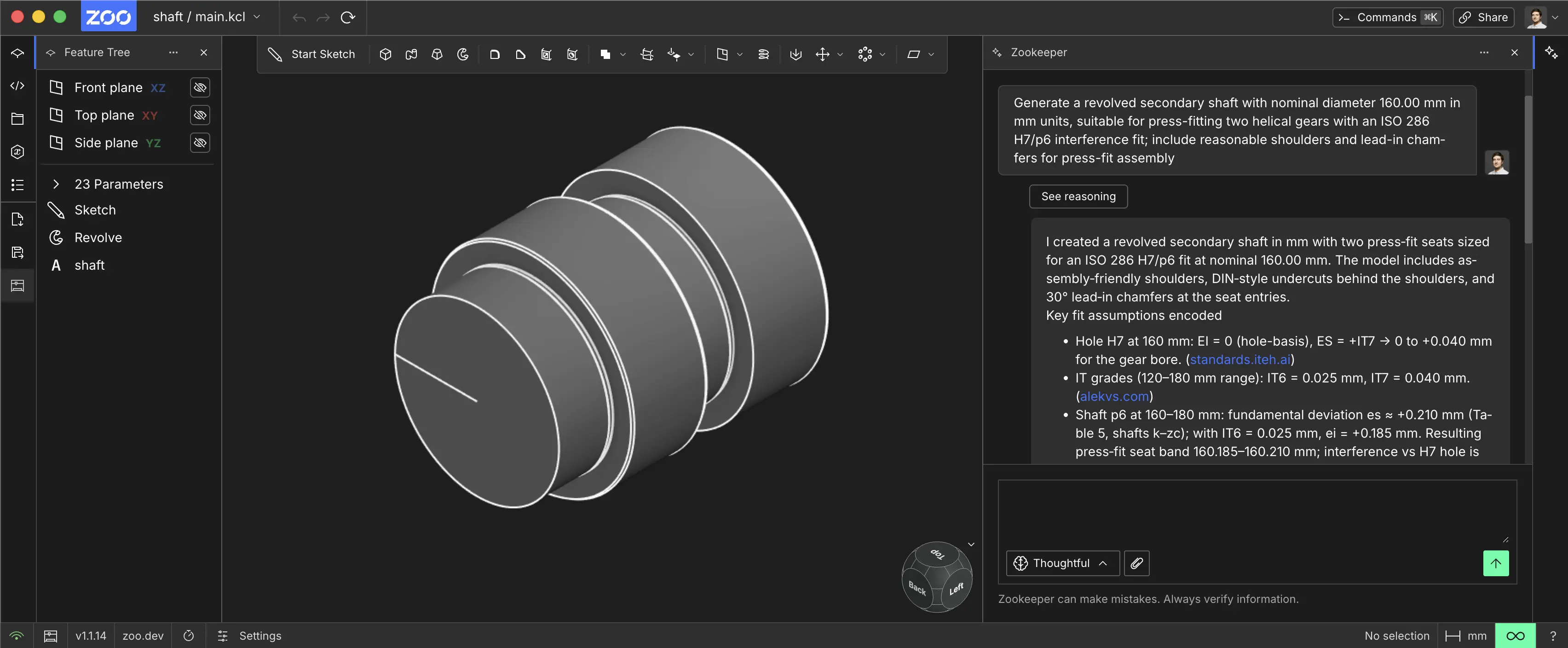
CAD-first, native, editable B-rep CAD with a parametric feature tree
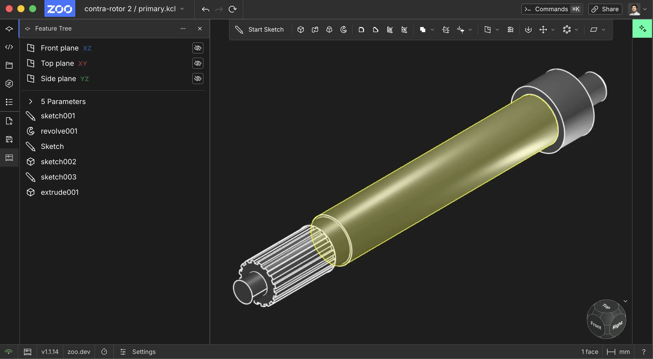
This approach produces true CAD geometry: B-rep with parametric history and a feature tree. Engineers can edit it, constrain it, and manufacture from it directly.
It supports standard workflows like selecting a face or edge and using it to drive machining operations.
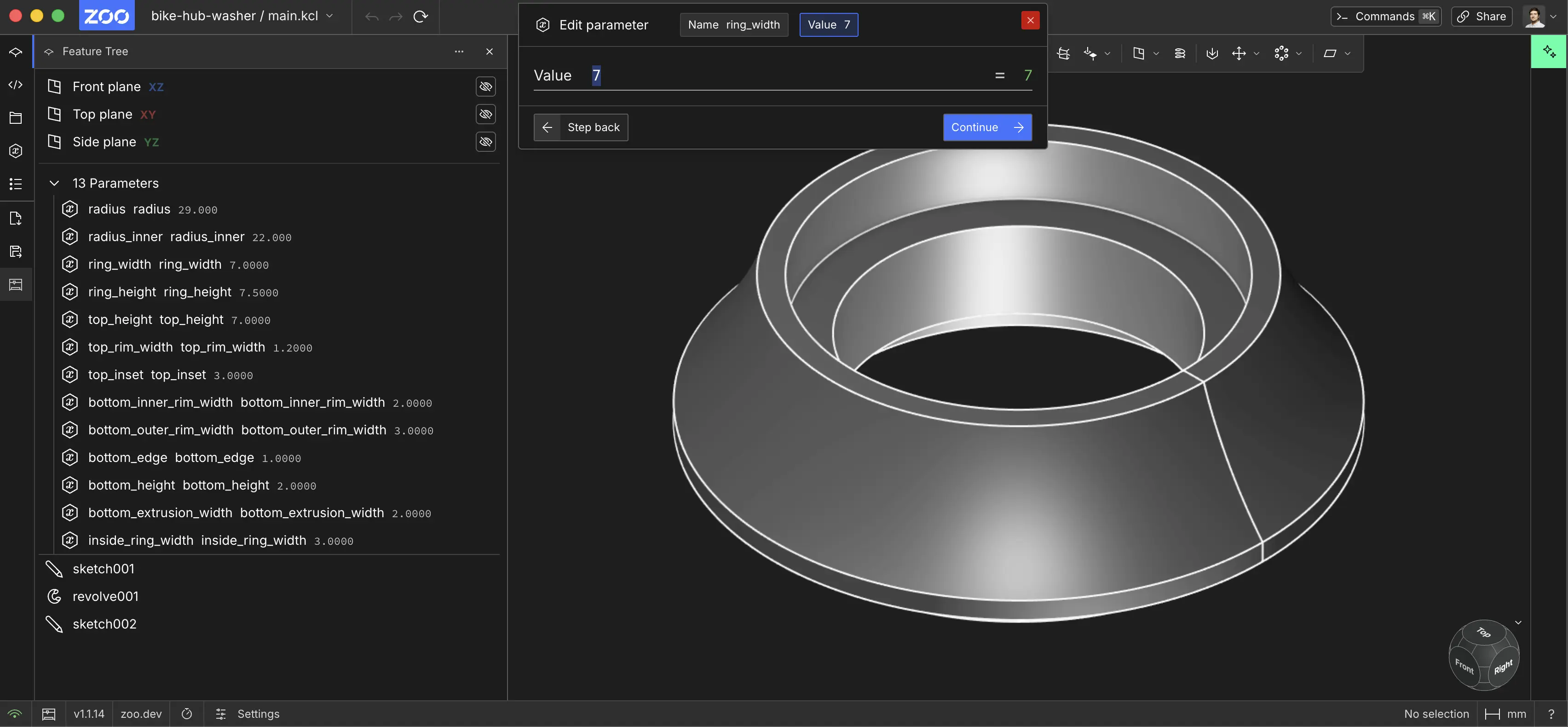
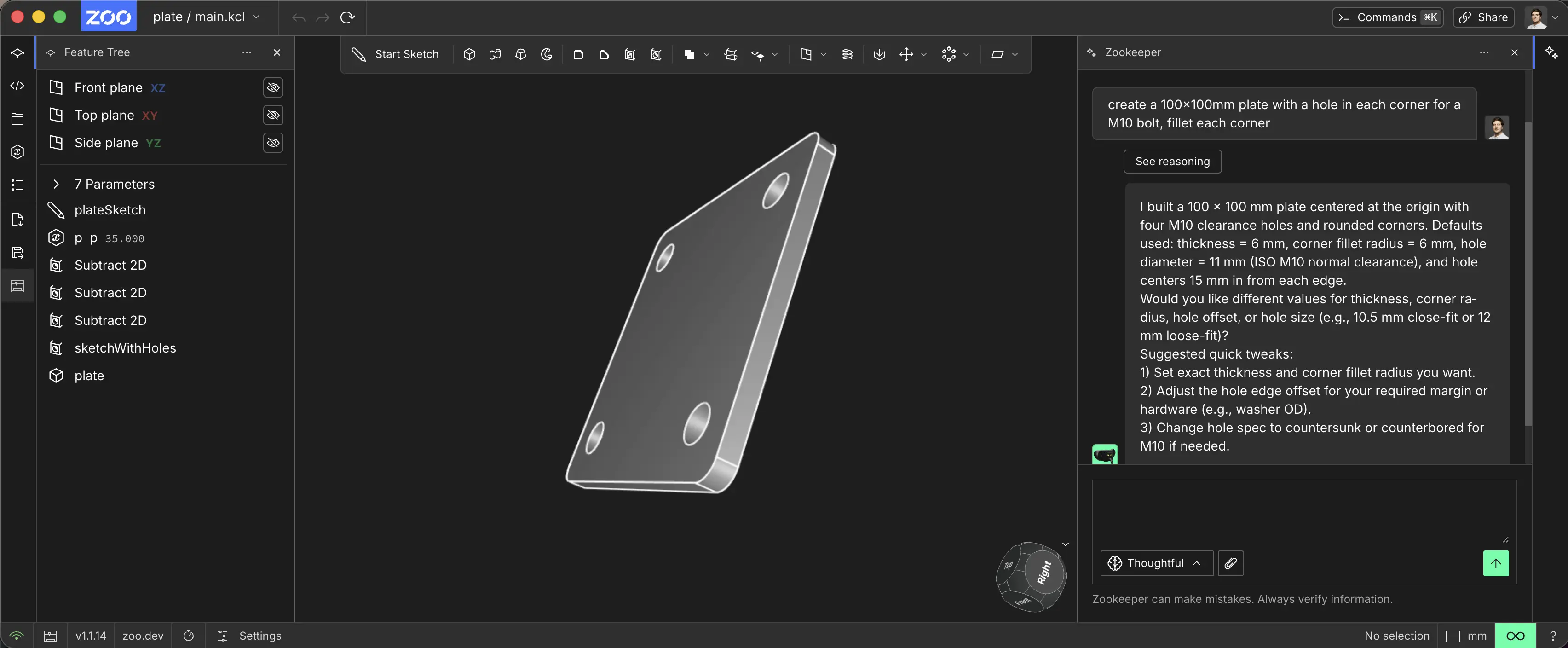
Parametric CAD captures engineering intent, not just geometry. The feature tree encodes driving dimensions and constraints (hole spacing, overall width, symmetry), so edits stay predictable.
This is the CAD-first approach.
Mesh-first generation (non-editable CAD output)
Many of our competitors still rely on mesh-first pipelines. They often use diffusion or related methods to produce intermediate 3D representations (implicit fields, triplanes, voxels), then extract a triangle mesh.
This makes it easier to produce something that looks like an object, but the output is still raw surface geometry, not editable parametric CAD.
It is like training on compiled output instead of source code. You can see the result, but you have lost the structure that makes changes reliable.
Mesh-first pipelines introduce major issues:
-
Incomplete geometry (single-view / diffusion model): When a mesh is generated from one or a few images (or partial scans), unseen regions (backsides, occluded cavities, internal faces) are underconstrained. Models often guess or leave gaps, producing missing surfaces, non-watertight shells, or inconsistent thickness - so the result can’t be trusted for CAD or manufacturing
-
Not CAD-compatible: A mesh model may look correct, but it’s still just triangles - without parametric BREP, feature history, or engineering intent. There are no driving dimensions, constraints, or feature logic, and no stable CAD topology (faces/edges) to drive standard CAD/CAM workflows.
That is why generating true parametric CAD from the start is fundamentally better for mechanical engineering.
Why meshes will never work for mechanical engineering
A triangle mesh is an approximation of a surface, not a definition of engineering geometry.

Even when a mesh looks perfect, it collapses the things CAD/CAM depends on:
- No analytic intent: In CAD, a hole is a cylinder with an axis, diameter, depth, and often a spec (clearance, tapped, counterbore). In a mesh, a “hole” isn’t empty space, it’s just part of the mesh defined by surrounding geometry. There’s no axis to reference, no diameter parameter to change, and no stable feature semantics.
- Unreliable selection: CAM and inspection workflows need to select faces (planar faces, cylindrical faces), edges (silhouettes, tangency breaks), and datums (axes, midplanes). On a mesh, you’re selecting triangle soup. Even if software tries to infer primitives, it’s a best-effort guess.
- Mesh-to-B-rep is surface fitting, not recovery: “Just convert the mesh to CAD” sounds reasonable until you do it at production tolerances. A mesh inherently contains less information than a B-rep. Trying to recover that information into a B-rep model typically involves fitting analytic surfaces to the noisy, discretized mesh, then stitching and healing gaps.
- No feature tree: Even if you somehow recover a watertight B-rep, you’re still missing the parametric history that makes edits resilient. You can’t roll back to “before fillets,” change a sketch dimension, then replay the operations. You’re stuck with direct edits, which are brittle under iteration.
- Unstable topology: Engineering workflows implicitly rely on stable references (“this hole pattern,” “that mounting face,” “the axis of this boss”). In mesh-first pipelines, any regeneration or conversion step tends to reshuffle topology. Faces split, edges reorder, IDs change. Downstream constraints and references break.
Meshes have a place (rendering, scanning, visualization), but they’re fundamentally the wrong working format for iterative, manufacturable CAD.
Why voxels will never work for mechanical engineering
Voxels are 3D pixels: a grid where each cell is filled or empty (or stores density). That makes them intuitive for ML, but fundamentally incompatible with precision CAD.
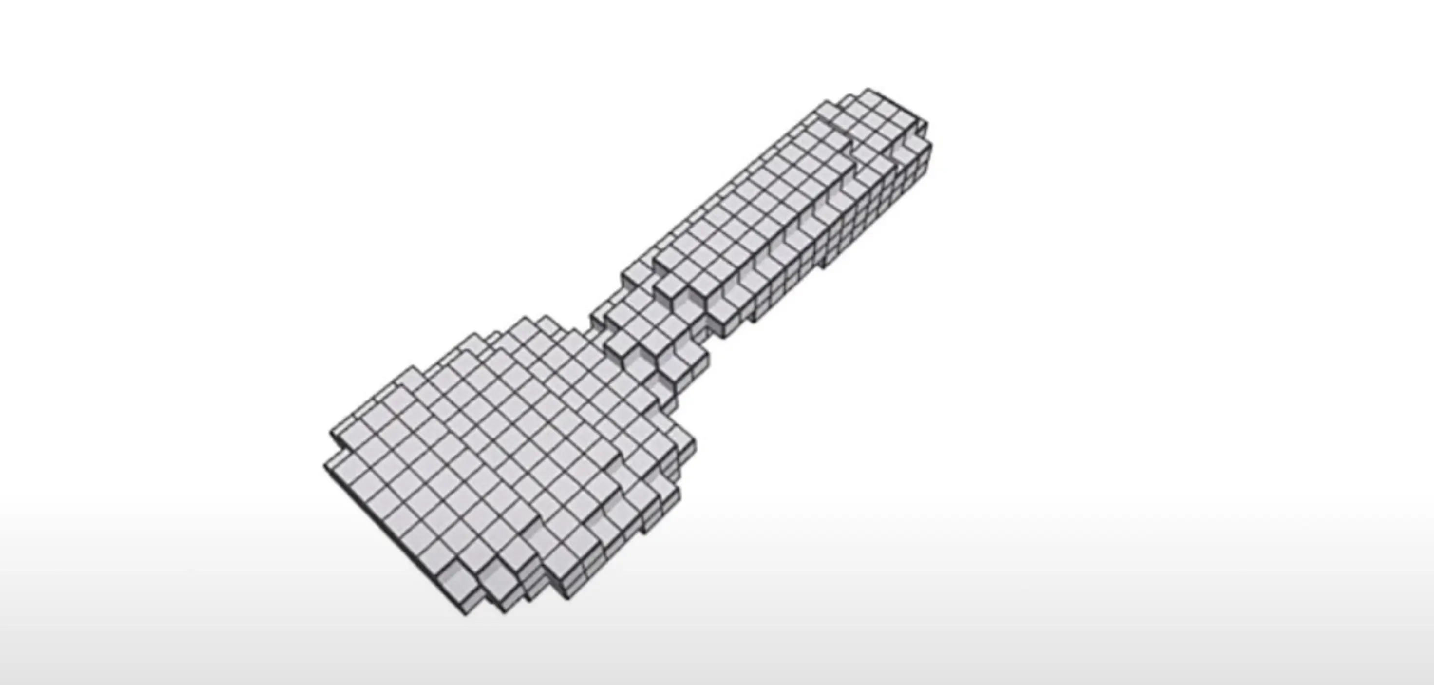
- Resolution destroys practicality. Mechanical parts live in millimeters and tolerances. If you want to represent a 200 mm part and resolve 0.05 mm detail, you’re talking about a grid on the order of 4000³ cells. That’s not a “slightly bigger model,” it’s a different universe of compute and memory.
- Stair-stepping is not an edge case, it’s the default. Curves, fillets, draft angles, and smooth blends become jagged approximations unless the resolution is absurdly high.
- Voxel → surface extraction is still mesh-first. The moment you need a boundary (for CAM, FEA, drawings), you extract an isosurface and you’re back to a triangle mesh. All the same problems reappear: approximation, ambiguity, no feature semantics, no parametric history.
Voxels can be useful as an internal representation for research or coarse concepting, but they don’t solve the core requirement: native, editable CAD.
The CAD Recipe
What “CAD-first generation” actually implies: Generating manufacturable CAD is less like “generating geometry” and more like “generating a parametric recipe.”
A real part comprises several intentional operations:
- Sketches with constraints (symmetry, tangency, equal, concentric)
- Dimensions with design intent
- Features (extrude, revolve, shell, draft, fillet, chamfer)
- Patterns and mirrors
- References (datums, midplanes, axes)
- Clear structure (named parameters, coherent feature order)
That recipe is the real artifact engineers work with. The solid is computed output.
The core capability is not to produce triangles that resemble a bracket. It is to produce a robust parametric model that behaves like an engineer built it.
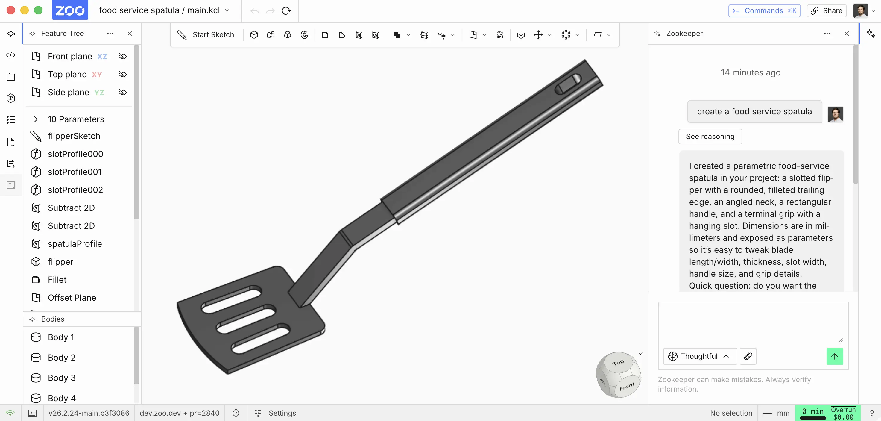
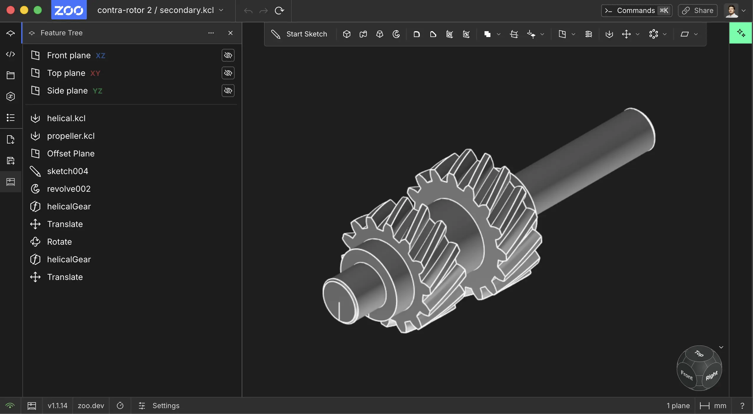
What Zoo’s approach unlocks
Because CAD-first systems generate parametric B-rep directly, output is usable in the workflows that matter:
- Iteration without rework: change a dimension, regenerate, and continue.
- Manufacturing-ready geometry: stable faces and edges that CAM tooling expects.
- Downstream compatibility: move into machining and inspection without betting on fragile mesh or voxel conversion.
- Intent-preserving models: the model captures why geometry is shaped that way through constraints, dimensions, and feature structure.
Zookeeper, our CAD agent, uses AI to generate and modify parametric B-rep CAD models through KCL.
If you're curious about the language behind that workflow, learn more about KCL, our code-based CAD language. From there, you can dive into the language reference, the standard library, and sample CAD models written in KCL.
Closing
Mechanical engineering is not about producing a shape that looks right. It is about producing a model that survives iteration and carries through manufacturing.
That’s why Zoo is CAD-first: generating manufacturable, editable parametric CAD from the start isn’t a nice-to-have - it’s the difference between a demo artifact and a tool engineers can actually use.