We're thrilled to announce we've completely redone Zoo's sketch mode, complete with a new, fully-integrated constraint solver. Early users say this makes designing 2D geometry much easier. The new constraint solver is fully integrated into Zoo Design Studio's point-and-click sketch mode, and the underlying KittyCAD programming language (KCL) that powers it. Our new sketch mode loosens restrictions and adds powerful new tools, like placing construction geometry and constraints. This should make Zoo a lot more familiar to anyone who's used industry-standard CAD software before. All users will get these features, free of charge, with the latest Zoo Design Studio update 1.2. We're excited for you to try it!
Here's an example of creating a basic plate in our new sketch mode.
Background: what is Sketch Mode and why does it need improving?
Sketch mode is where most users start building parts in Zoo. When you first open Zoo Design Studio, you see an empty 3D scene. Typically users choose a plane, and start sketching a 2D shape on it, which they eventually turn into a 3D solid (via extruding, revolving, etc).
All sketching is done in a dedicated 2D sketch mode. Users choose a plane or face to sketch on, the camera animates, revolving and swooping down to face that plane head-on, and then users can use their mouse to place 2D lines and curves on that plane. When they're done, they leave sketch mode, and can view their 2D geometry in Zoo's usual 3D view. Eventually they'll turn that 2D sketch into a solid.
So, the 2D sketch mode is a critical part of Zoo. It's the basis for creating almost all geometry. Our initial sketch mode had some limitations. It required users to think carefully about the order in which they created lines. For example, to create a basic slot shape, users had to choose a starting point, then add a straight line, a semicircular arc, another straight line of the same length, and another semicircular arc of the same diameter. They'd have to know how long each line should be, in advance. Sketching anything more than simple shapes required a lot of careful planning upfront. It wasn't ideal, and user testing quickly confirmed this. Our sketch mode was not living up to our expectations.
Most engineers don't start sketching with an exact plan for every line they plan to draw, in order, from the start to end of all their 2D shapes. Instead, they draw rough guesses of the geometry, in any order they like. Once they've got a rough draft of the shape, they start adding in constraints – facts or requirements, like "these two lines should be parallel" or "these two lines should be the same length". As the engineer adds more constraints, their initial rough draft geometry starts snapping into its final place, and eventually the sketch is fully constrained: no data from the rough guesses or initial draft is left. Every line and point is exactly where it needs to be.
Our first sketch mode made users do all this work upfront, requiring every line to be placed exactly where it should go, with no margin for error. But our new sketch mode lets engineers place geometry in its rough position, then add and remove constraints until their sketch is perfect. Our internal employees and users say they can get work done "at least 10 times faster" in the new sketch mode, and that it enables "serious mechanical engineering that wasn't possible at all in the previous UI."
How our new sketch mode works
Let's say you had to sketch a rhombus, with diagonals of length 10cm and 15cm. In the old Zoo sketch mode, there was no way to explicitly dimension these internal lengths. I had to do some basic trigonometry on pen and paper. This is not a good experience for mechanical engineers. Serious CAD software should not make its users do trigonometry.
In our new sketch mode, though, this is pretty easy!
I select the line tool, sketch 4 lines, then select them all by dragging with my mouse. I'll select a pair of opposite lines and make them parallel (via the "Parallel" constraint, or the keyboard shortcut B), then do the same for the other pair. Next I'll add the diagonals with the line tool, and make them construction geometry, since they're only being used for dimensioning, and aren't needed in the final solid. I'll select one diagonal and press the Dimension button (or D), double-click its dimension and change it to 10mm. Then I'll dimension the other diagonal to 15mm.
At this point, the shape looks right to me, but if I start dragging one of its points around, I notice it's not fully constrained yet – the diagonals can be at any angle. Let's fix that by making them perpendicular to each other. Now the shape is constrained – I can try dragging points around, but they're locked in place relative to the other points. The sketch is still blue, though, indicating that it's still underconstrained. Indeed, I can move the overall shape even though its dimensions are fixed. So let's fix one vertex to the origin. Now it's anchored to the origin, but I can still rotate it around. So I select one of its diagonals, and make it vertical (via the Constraint > Vertical button, or pressing V). Now the sketch has turned white, meaning it's fully constrained. Corroborating this, I can't move it around anymore – there are no degrees of freedom left.
This is how mechanical engineers are used to working. They start with some requirements, hand-draw a vague approximation with the mouse, then apply constraints until it's perfect. Our internal users say that the new sketch mode is both easier to use and more powerful, allowing them to build parts they couldn't have completed in the old sketch mode.
When you sketch, you create closed 2D shapes. These are called regions. You can select one or more regions when building a 3D shape (e.g. with the Extrude or Revolve tool).
You can also use the Trim tool to quickly remove lines you don't need anymore, breaking geometry into smaller pieces where it intersects. This really simplifies creating complex sketches! Take a look at this quick demo:
The ezpz constraint solver
This is all powered under the hood by a new constraint solver library we've built. We call it ezpz, and it's a totally free, open-source (MIT licensed) constraint solver written in Rust. We'll be publishing a blog post with more technical details soon. For now, you can check out the code on GitHub. We built ezpz because existing constraint solvers were either expensive or had restrictive licensing. We're hoping that by making ezpz a free, open-source, community project, it'll help other people build their own interesting geometry applications. Ezpz is written in Rust and works great in-browser or in native code.
Coding in KCL
Mechanical engineers love the new point-and-click constraint solver, but programmers can also access this powerful new tool. All Zoo models are actually, under the hood, stored as code. If you open up the Code panel, you can view this model's source code. It's written in KittyCAD coding language (KCL).
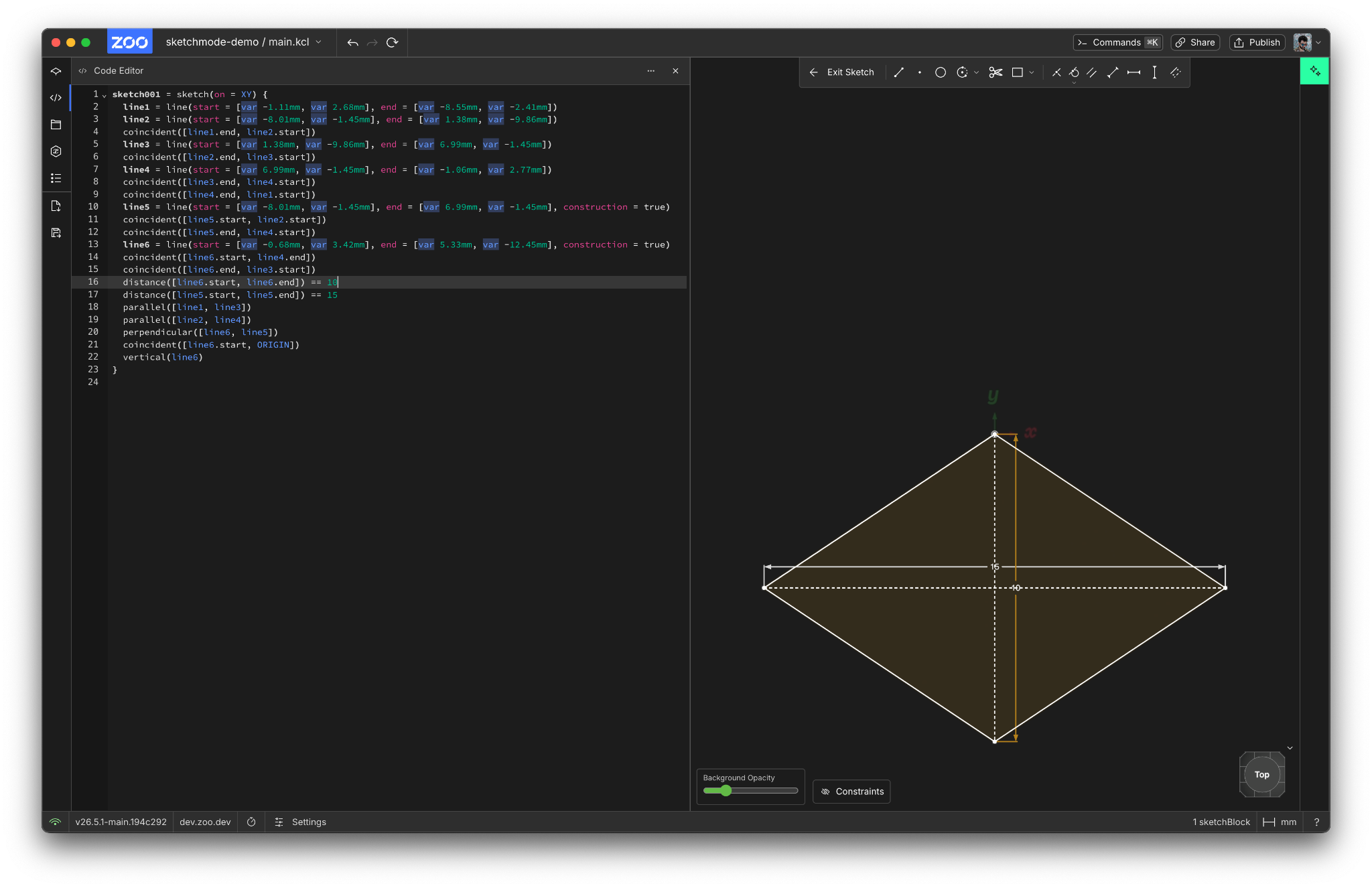
This code is human-readable, but it was generated by the point-and-click UI actions I took. I'm a programmer, so I like my code to be neat. So while I've got the code panel open, I'm going to add some comments, organize my code into related themes, and rename some variables so I know which lines are diagonals and which are edges.
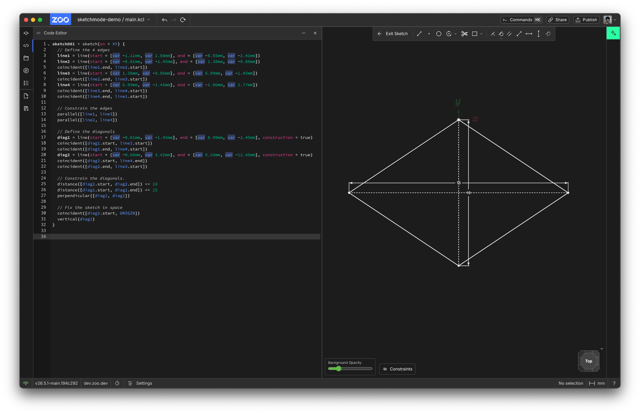
There, that's better. You can see KCL's new "sketch block" syntax, where I open a sketch on a certain plane (XY) on line 1, and then add geometry and constraints within the block. Sketch blocks let programmers declare their intent, just like mechanical engineers do. Previously, KCL made you specify each line of geometry exactly. But now, programmers can define underspecified geometry and add constraints to it, then let the constraint solver work out the exact position of every little point and line.
KCL is a single unified representation of your CAD model, but you can edit it however you want: via Zoo's traditional CAD point-and-click interface, or writing code in the text editor of your choice, or using Zookeeper or some other LLM to turn your prompts into geometry. You can mix and match these approaches: like in the above example, where I generated most of the model by hand in the point-and-click GUI, then cleaned up the code afterwards. You could get an LLM to give you a starting point, then tweak it in our point-and-click editor or by opening the KCL code in your terminal.
We're really excited to see what you make in Zoo's new sketch mode. You can use it now, for free!