Why I joined Zoo
- On the importance of engineering
- Why our design tools matter
- A brief history of post-Renaissance design tools
- A note on modeling paradigms
- Geometry representation schemes
- Which is most appropriate?
- Direct vs. parametric modeling
- Parametric B-reps, please
- From paper, linen, and film...
- To some of the most complex software ever built
- So why can't we make things like we used to?
- What can _we_ do better?
- Kernel panic
- Mathematics doesn't rust... but the world around us has changed
- On collaboration, file formats, and API access
- Bandwidth, input modalities, and...
- *The big pile of linear algebra*
- An anecdote from the next discipline over
- Code CAD, multimodal input, and the design bottleneck
- Why I'm excited about Zoo
- Hard problems and smart people
- Domain expertise and the structure of the universe
- Work worth doing
About the author
This is my first post since joining Zoo, so before I dive into my motivation for joining the team, I want to provide some personal background—mostly for the benefit of any mechanical engineers arriving here, wondering whether a software startup might have any real appreciation for the problems that they face.
My professional experience now crosses over into other realms, but I studied Mechanical and Manufacturing Engineering at university, and I began my career as a mechanical engineer in Formula One. Over the course of seven seasons, and across both powertrain and chassis development, I butted up against a pretty broad range of engineering challenges.
Though most of my time was spent on 'performance development'—crunching numbers, developing analysis tools, designing experiments, running rig tests, and performing simulation studies—I’ve also devised procedures for inspecting components, overseen the installation of imaging equipment, designed tools to support build, and served time as a mechanical designer. That design experience covers everything from the most minor washer chamfer detail through to wholesale redesign of big chunks of critical systems.
Since then, I've worked as a signal processing engineer in the biomedical space, a software engineer in both quantitative finance and defense, and founded and run an ill-fated engineering collaboration startup. I care deeply about engineering tooling, about improving engineering productivity, and about empowering engineers to improve our future.
Nomenclature
At the risk of upsetting software colleagues current and former, I should point out that when I use the term engineering here, I'm generally referring to the physical disciplines: mechanical, aerospace, civil, structural, electrical etc.
On the importance of engineering
This is paraphrasing from a presentation I delivered a couple of years ago, but worth repeating: engineering is of critical importance to our success as a species. Almost every man-made object you ever encounter is the product of an engineer's efforts.
Without engineering, we would not only have to forego cars and airplanes, but almost the entirety of humanity's tech tree. We would not have central heating or air-conditioning, roads or airports, apartment buildings, running water, sanitation, modern medicine, or mechanized agriculture. Both our way of life and our lives themselves depend on our ability to make things.
Why our design tools matter
We have been making things, and making tools, for as long as our species has walked the earth. The tools we use shape our environment, our behavior, and our way of life. Every advance in the capability of our tools yields an advance in what we can do with them.
A brief history of post-Renaissance design tools
Focusing on engineering technology that has been developed in modernity (sorry Vitruvius), I see around twenty key developments between John Napier's invention of the logarithm and our current CAE suites.
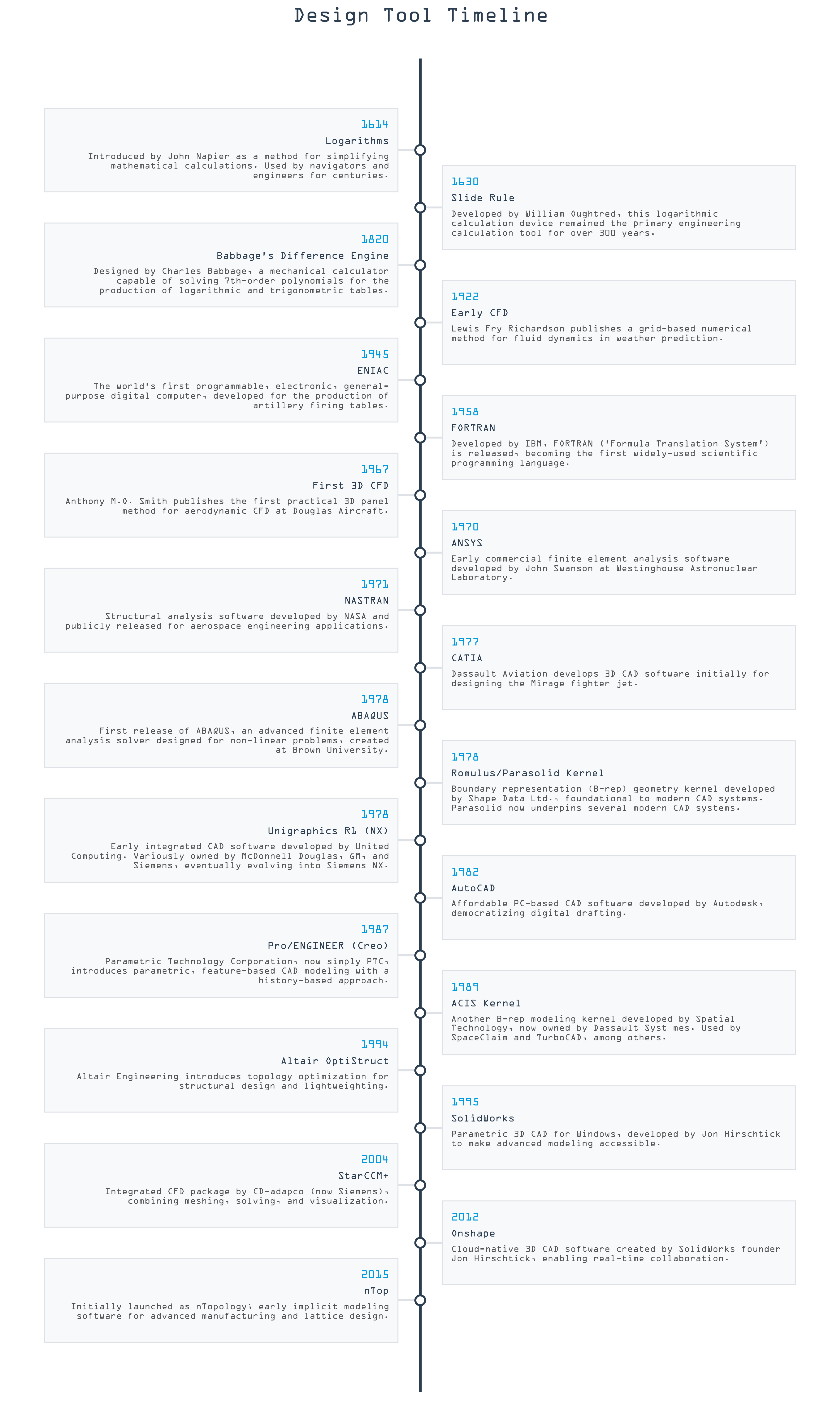
If we group these development by decade, an interesting phenomenon emerges. The plot below shows relatively infrequent developments as we move from Napier to WW2.
The post-war period, however, tells a different story. Driven by the semiconductor revolution, the 1970s is a golden era for engineering design tools. Between 1970 and 1978, we saw the first incarnations of ANSYS, NASTRAN, CATIA, ABAQUS, Parasolid, and NX.
By the 1990s, new releases had slowed, with SolidWorks probably the most influential new arrival of the time. The 90s and 2000s saw a glut of acquisition and consolidation activity, with Siemens, Autodesk, and Dassault Systèmes scooping up many of the smaller players.
Through the 2010s, the most influential new products were probably Onshape and nTop. Onshape brought a modern, collaborative paradigm to the space, while nTop is the most prominent implicit modeling system that I'm aware of. This period also saw the foundation of Shapr3D, a much-lauded, modern CAD system that addresses the long-standing user hostility of incumbent CAD systems, while continuing to build on the Parasolid kernel's foundations.
A note on modeling paradigms
This is a nuanced point that I feel is often glossed over by those who are not deeply involved in the space, but while on the topic of CAD system history, it is worth providing some context on the modeling paradigms available to us.
Geometry representation schemes
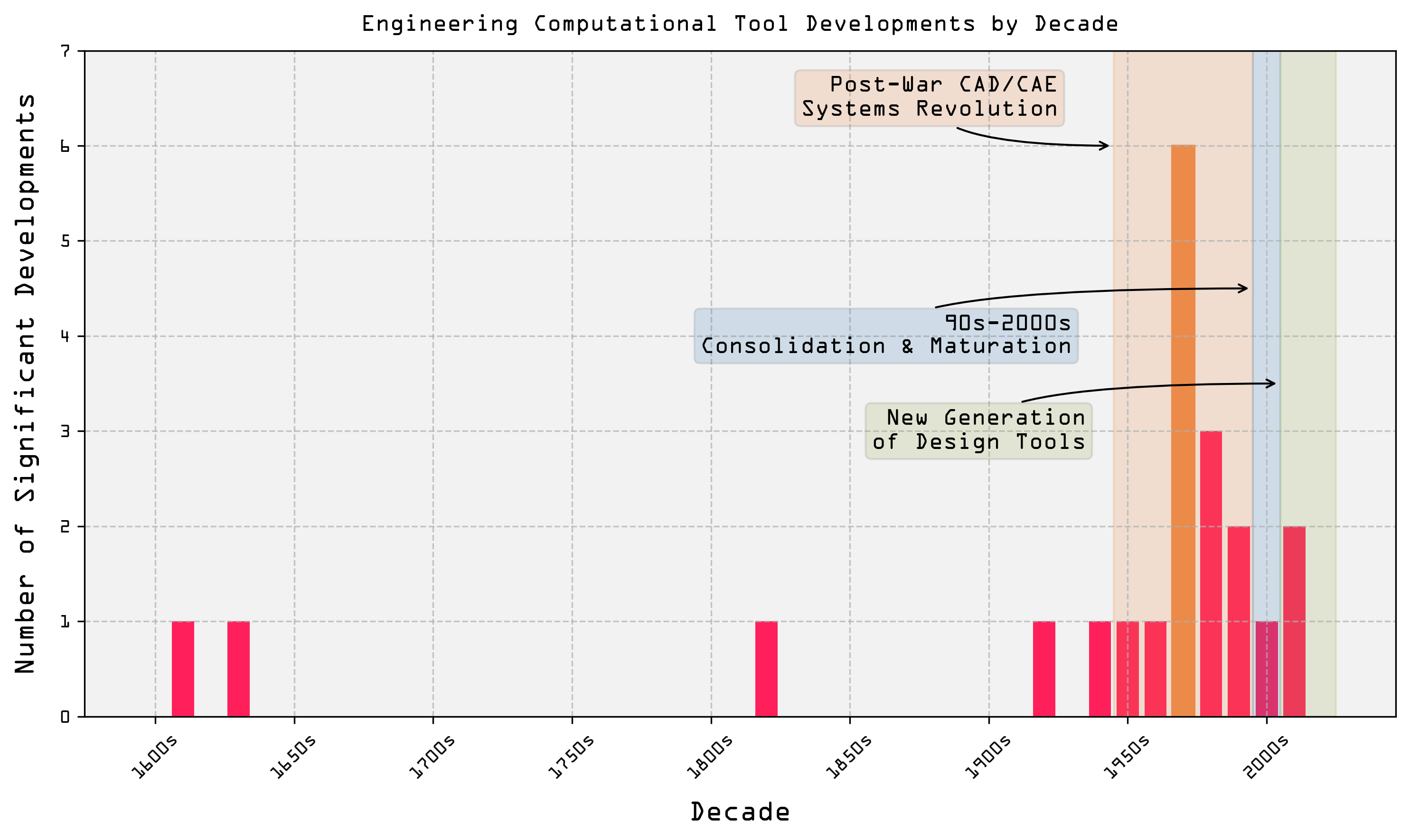
Before we touch on how a designer would actually compose anything with extrudes and sweeps and lofts, we first need to iron out a mechanism for describing the geometry of an object. To represent a shape in three dimensions, there are three methods I think are relevant here:
Boundary representation is a mathematical description of an object that defines its boundaries using curves and surfaces. It explicitly defines object geometries using mathematical descriptors of their surface boundaries—faces, edges, and vertices—which collectively represent a precise description of the object's shape. A B-rep stores both the topology—the connectivity of faces, edges, and vertices—and geometry—the exact spatial positions, dimensions, and shape definitions—of each element. They can incorporate multiple geometric primitives, including planar surfaces, analytical shapes (like spheres or cylinders), and parametric curves and surfaces such as NURBS. The inclusion of NURBS within B-rep models is particularly significant, as it enables smooth and precisely controllable representation of curved surfaces and edges. This broad precision makes B-reps valuable for applications where geometric accuracy and manufacturing precision are important. Every major mechanical CAD system employs a B-rep kernel.
Implicit representations differ significantly, as geometry is described through implicit mathematical equations, rather than explicitly through boundary surfaces. In practice, this involves evaluating points in three-dimensional space to determine whether they're 'inside' or 'outside' the defined shape. Implicits are well suited to representing highly complex, computationally derived shapes, and are naturally suited to employment in highly iterative workflows, e.g., when included within an optimization loop. However, implicits may require computationally intensive conversion into alternate representations before detailed design edits or manufacturing become feasible.
Polygonal meshes define geometry through collections of simple polygonal facets—most commonly triangles or quadrilaterals. This representation is computationally efficient, universally supported, and ideal for visualization. Mesh formats are also commonly used in 3D printing. However, in the context of mechanical design workflows where limits and fits matter, and where geometry must be tightly controlled, meshes lack precision and any element of parametric editability. As a result, they are largely unsuitable for engineering workflows where precise specification of design intent is critical. To edit a mesh, you cannot directly adjust a diameter or a length; you have to adjust vertex and edge locations in a 'dumb' sampling of the shape in Cartesian space.
To give some idea of how these work in practice, here are three representations of both a circle and a sphere.
The first is broadly how a B-rep would work. It's an accurate mathematical description of the shape. The second is an implicit representation, where we evaluate a function whose result gets further from zero the further we move from the object's perimeter. The third is a polygonal mesh, where we've sampled the object around its boundary, and—at least in the spherical case—approximated the shape with a set of triangles.
Which is most appropriate?
Practically, these distinctions mean that boundary representations are effectively a hard requirement for real-world engineering of almost all mechanical systems. B-reps offer the combination of precision, robustness, and parametric control needed to actually describe a piston or a shaft or a gear.
Implicit models offer powerful methods for exploring highly optimized, organic shapes in applications such as high-performance heat exchangers and other lattice structures. They are also well suited to the generation of complex, generative designs, where the shape of the object is driven by ambitious performance criteria—like in some hypercars.
Meshes are for visualization and for feeding to 3D printers. They contain no depth of information about the geometry they represent, lack direct, dimension-driven editing capabilities crucial for precise engineering workflows, and are broadly irrelevant to the design of complex mechanical systems.
Direct vs. parametric modeling
Now that we have a handle on how we might represent the geometry of an object, we can consider how an engineer might actually assemble that object in their CAD system. There are two primary paradigms for this: direct modeling and parametric modeling.
Mentioned in passing above, parametric modeling is the dominant approach to mechanical design where you have clear requirements and need to specify strict manufacturing criteria. If you know that you need a shaft of a certain length, with a certain diameter, and with a certain style of keyway, you can define numerical descriptions—parameters—for each of those features in your CAD system and then use those parameters to drive the geometry of your part. Down the road, if you find your shaft isn't stiff enough, your new design doesn't have to be started from scratch; you can duplicate your original CAD model, adjust a length or a diameter value, and then the rest of the part's geometry will update accordingly. This approach is ideally suited to the design of machinery, where the engineer must integrate bearings, gears, and other components into a single, coherent system; parametric patterns allow multiple interdependent features to retain the desired relationships during modifications.
Direct modeling is more like working with clay. You can draw some primitives, then push them and pull them to build up the shape that you want. This approach is well suited to more aesthetically driven design, and perhaps in the earlier stages of machine development where concepts are being loosely explored, but it embeds no aspect of design intent in the model. If you need to change the diameter of a hole, you have to manually adjust every instance of that hole in your model—there is no ability to propagate related changes through the model based on a central set of parameters.
Parametric B-reps, please
For practical mechanical engineering workflows, parametric modeling with boundary representation is effectively mandatory.
Mechanical components almost always have strict requirements—precise tolerances, standardized fits, and clearly defined geometric relationships; exactly what parametric B-rep modeling is designed for. By explicitly encoding both geometric precision and some portion of the engineer's design intent, parametric B-rep models enable engineers to reliably ideate, develop, and communicate design details. Their explicit topological and parametric precision ensures consistency and accuracy throughout the design and manufacturing cycle, supporting everything from generating production-ready drawings to providing clean, well-defined input for downstream simulation... even if most simulation techniques will involve generating a mesh of their own!
From paper, linen, and film...
Having traced the development of design tools and discussed some foundational aspects of their operation, I think it's worth touching on the workflows these tools replaced...
Prior to the 1970s and the rise of CAD and CAE, 'design' really meant two things:
- Thinking up concepts, exercising engineering judgement, and crunching numbers with a slide rule or a calculator to perform simplified analysis.
- Producing, by hand, on paper, linen, or drafting film, detailed drawings of every single component in your system, with geometry, critical dimensions, and material selections dictated by the output of step 1.
This required teams of engineers educated in broadly the same way we are today; people who had studied structures and thermodynamics and materials science, and who were able to mathematically model the systems they were designing. It also required vast numbers of draftsmen, each hunched over a drawing board, producing meticulously detailed projections and cross sections of the components sketched out by their colleagues.
Changes required skillful use of an eraser, a knife, or a sponge and soapy water—but sometimes also mandated the production of a stack of amendments, or a complete redraw.
To some of the most complex software ever built
Without question, CAD has revolutionized the practice of engineering. In the space of a couple of decades, draftsmen were deleted from the process almost entirely, with their role being absorbed into the expected skillset of a professional engineer. Drawings were no longer confined to physical and often fragile media, and no longer had to be painstakingly hand-crafted. Drawing changes became cheap and painless, and designs could be shared electronically.
The software that enabled this shift, our CAD and CAE tools, are some of the most intricate and sophisticated software systems ever created. A modern CAD system is a deeply challenging thing to build, requiring the input of actual subject matter experts in both mathematics and computer science. To represent the geometry of even the more simply shaped everyday objects around you, these software systems must be capable of implementing and applying complex mathematical operations to often incredibly large datasets.
Given that, our incumbent systems are already triumphs of human endeavor; the output of collaboration between computational geometers and programmers and engineers of several kinds. They let us iterate more quickly, explore more options, and push system performance more than ever before.
So why can't we make things like we used to?
This point is slightly facetious, as we clearly are capable of engineering more complex and more performant systems than ever before.
For example, in civil aviation, the newest incarnations of high-bypass turbofan engines are incredible multidisciplinary accomplishments, pushing the limits of materials science, manufacturing technology, and computational simulation. Not only can they run for 5000 hours between inspection cycles, they do this while accommodating combustion temperatures that can be well in excess of the melting point of all engine materials. They also contain turbine blades that are the product of probably the most impressive manufacturing technique that I'm aware of: single crystal casting.
Back on the ground, you are probably entirely familiar with how much better a modern car is than its equivalent predecessor vehicle was two decades ago. They are safer, faster, more comfortable, more refined, and significantly more efficient. It's easy to miss this broad-spectrum improvement in the quality of products around us because of that improvement's incrementally advancing nature, but this trend is evident almost everywhere. Sofas no longer burst into flames if you drop a cigarette on them, pocketable smartphones have more computing power than mainframe machines from a few decades ago, and doctors have access to surgical robots that would be unimaginable to surgeons trained a generation prior.
However, in some respects, we really do seem to have gone backwards—particularly if we look at how long it takes us to bring new products into existence.
The now discontinued Airbus A380, one of the most recently developed major civil airframes, was first announced in 1990, but didn't take flight until 2005. In contrast, the North American Aviation P-51 Mustang prototype was designed and built in 120 days. Lockheed's SR-71 Blackbird, the fastest publicly acknowledged airbreathing manned aircraft ever, was designed by a team of around 200 engineers and first flew within around five years of its inception—and this extended well beyond the design of an airframe, encompassing the development of manufacturing techniques, materials, fuels, navigation systems, and extensive redevelopment of the Pratt & Whitney J58 powerplant.
In the civil space, the Empire State Building moved from initial concept to completed structure in just over two years—planned and designed within six months, then constructed in just 14 months. On my side of the Atlantic, Crossrail was delivered more than £4B over budget, and five years late. In Germany, planning for the much-needed replacement for the ageing Schönefeld and Tegel airports began in 1992, but didn't actually open its doors to the public until 2020; ten years late, and €5B over budget.
In many cases, this phenomenon can be at least partially attributed to a rising tide of regulatory requirements and increased expectations. Our professional antecedents would not have spent £100M on a bat tunnel. They would not have spent months or years consulting nearby residents or environmental groups, they didn't design vehicles to protect their occupants, and they were not subject to the same hardware and software certification processes that many industries face today. They also bundled test pilots into dangerous aircraft, strapped racing drivers into dangerous cars, and designed bridges that collapsed less than a year after construction.
So it is patently obvious that things are not 'worse' for no reason. As the saying goes, the rules of aviation safety are 'written in blood'—and I think the same could apply to many construction regulations, environmental regulations, and the driver and rider protections we now see in modern motor racing.
However, I don't think we can, in any degree of good faith, sit here and claim that the way in which we design and develop systems has no hand in the creeping drag on progress in industrialized societies.
What can we do better?
Despite the many benefits afforded by the last century's shift to digital engineering tools, it is not at all clear to me that we, the engineers, can actually ship production drawings for new systems any quicker than our grandfathers did.
Why is this? Well, the impression I have is that much of the time saving offered, or at least touted, by digital transformation has been cannibalized by expansion of the work that we do.
Before FEA and CFD, when the analysis methods involved lookup tables and crunching matrix math with a pen and a slide rule, there simply was no FEA† to do. By virtue of the analysis methods being organizationally expensive, i.e., taking your smartest people a long time to do, there existed a system that disincentivized small, marginal tweaks that would require everyone else to reconfigure their work. Instead, at least as far as I can tell from those who were there and who have written about it, numbers were worked out, fed to the draftsmen, and the parts were drawn up. The parts were then manufactured, tested, the results of the experiments assimilated and analyzed, and then maybe you went around the design-build-test loop again. This is a very straightforward process. It didn't require ruminating on software stacks or vendor integration—no need to worry about that when the tools of your trade are paper, pens, pencils, stencils, and your brain.
In contrast, contemporary design processes could now involve half a dozen different specialties, each with their own stack of specialist tools, putting forward their own priorities before anyone strikes a line on a (digital) page. As a result, even though we are now able to produce a modification to a part's geometry and to communicate that with a machine shop in dramatically shorter order than fifty years ago, I don't think the first drawing from a clean sheet design really arrives any quicker... even if the product will likely perform better than the grandfather version.
Beyond bigger teams and a Parkinson's Law-esque element of scope creep, I feel it is also worth considering the CAD systems specifically. Today’s CAD software, in large part, emulates its analog ancestors, mirroring workflows that were developed for drafting tables rather than networked supercomputers. Paraphrasing the thinking of a Twitter mutual, CAD really ought to stand for Computer Aided Drawing—because we're all still doing half the design work with Microsoft Excel or a notepad and a Casio pocket calculator. As for the other half, we're doing that with software systems which, despite their immense power and utility in the creation of complex geometries, have steep learning curves, a hostile user experience, poor interoperability, and which restrict computing hardware and operating system choices.
The fact that engineers spend so much time with these systems makes them, in my view, an obvious place to try and improve productivity, with today's CAD tools increasingly recognized as having a highly negative impact on engineering productivity:
For context, in the simulation world, many tasks involve a degree of 'waiting around'. A simulation engineer could spend a couple of hours building a study that could take many hours to run, but while the model is running, the simulation engineer is freed up to do other value-added tasks. As a result, a marginal increase in solver performance, for example, may not actually be that valuable, as the engineer is not blocked from being productive while the simulation runs.
In contrast, in CAD land, the entire process is effectively bound by user I/O. CAD systems are highly interactive, requiring continuous real-time input and response from users in order to advance the design. This makes CAD systems a clear target for improvement, because the CAD user cannot do anything else productive while using their system. Any improvement, however marginal, to CAD productivity will be realized thousands and thousands of times.
† Technically, you could trace the origins of the finite element method back to the early 1940s, but I really mean something akin to 'before finite element tools for structural simulation were commonplace in engineering'.
Kernel panic
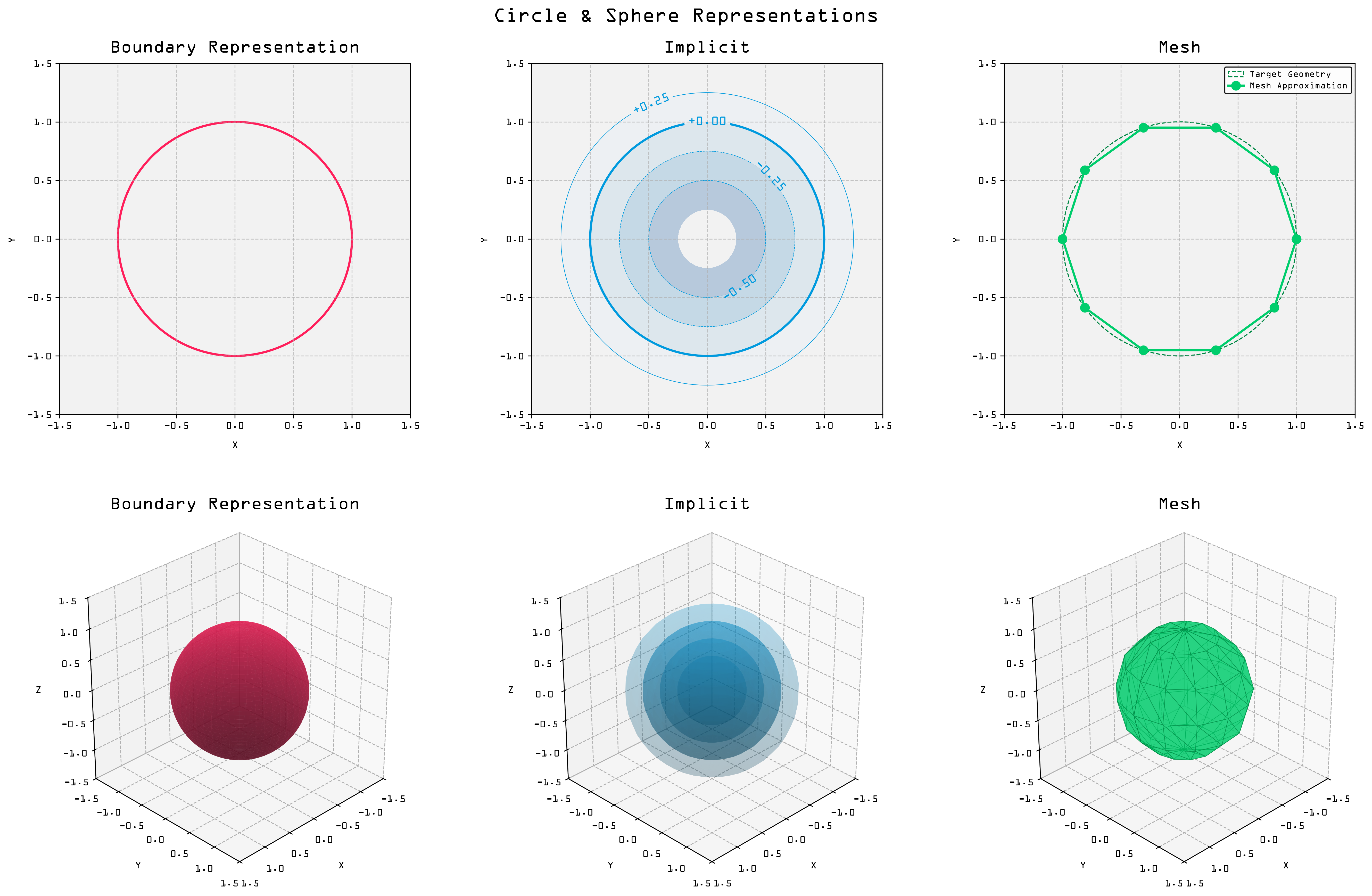
The term 'kernel' appears in this post a few times—but we still haven't really explained what we mean by it. For the uninitiated, a geometry kernel is the core computational engine within a CAD package; the program responsible for doing all the heavy B-rep lifting described above.
Today, the majority of the western world's CAD and CAE systems are built on either Parasolid or ACIS, though some major products from Autodesk, PTC, and Dassault Systèmes do break the mold†.
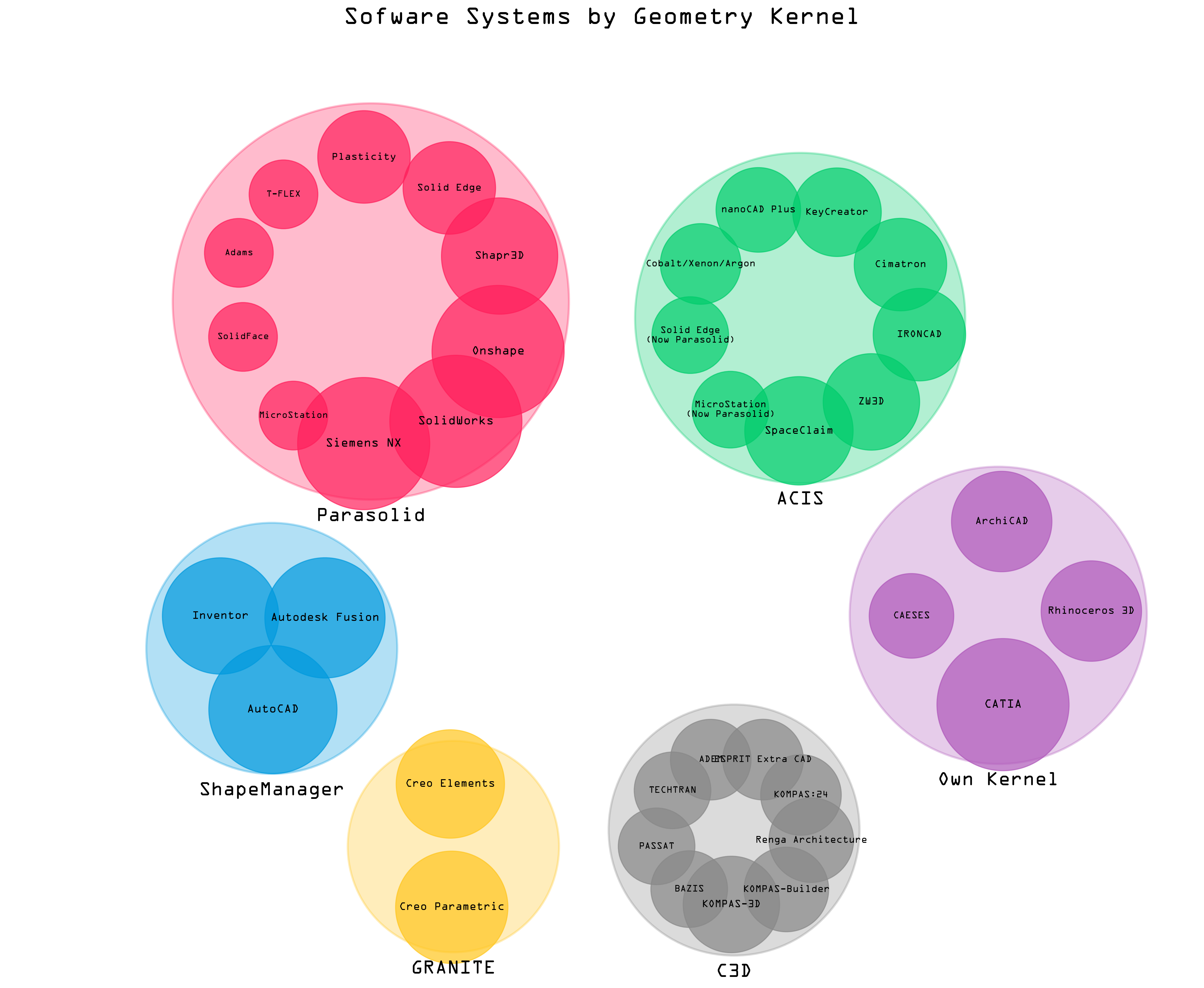
As the visualization shows, the kernel market is highly concentrated—but it's also largely static. Both Parasolid and ACIS were first release decades ago, and while this is not a problem in and of itself, it does mean that these systems come with some practical constraints.
† A parallel universe of Russian tools also exists, but these are completely alien to me.
Mathematics doesn't rust... but the world around us has changed
I have no desire to disrespect the foundations of modern engineering software. Engineering software packages are tools, and the mathematics that underpins them does not rust. A B-rep method does not become less useful because it was written in FORTRAN, or because it uses a programming paradigm we now consider old fashioned.
However, the way in which we use computers has changed dramatically since the 1970s. Each of us now has several machines, each of which is capable of sharing vast quantities of information with the other. Computer architecture itself has also changed. A typical CAD workstation today might have a 20 core CPU running at more than 5GHz, alongside a GPU that, although nominally intended for graphics, excels at performing large numbers of calculations in parallel. We use these machines to run software that was written for single-core, CPU-only systems.
I did not study Computer Science and have no formal training in computational geometry, so no warranty express or implied here, but my understanding is this:
- For B-reps, some common tasks in a CAD system are 'embarrassingly parallel', e.g., sampling curves, performing intersection checks. Others require largely sequential processing, e.g., graph-based operations on topology structures.
- For NURBS, evaluation of points and patches is amenable to parallelism, while knot insertion and degree elevation is not.
- Finding the intersection of NURBS surfaces is computationally expensive, and would require surfaces to be broken into patches then merged if intersection tests were to be parallelized.
- For constructive solid geometry (CSG), where we need to perform repeated Boolean ops across a tree data structure, there is some opportunity to parallelize 'bounding volume hierarchies', but the speedup is likely to be bounded by the topological merge required to assemble a final boundary representation.
That is not nothing; while the overhead involved in moving data between CPU and GPU should not be ignored, some large portions of the CAD kernel's responsibilities do seem to be amenable to rearrangement to suit modern computer architectures.
On collaboration, file formats, and API access
The evolution of our surroundings is not limited to compute hardware. There are three other areas I think we must improve, each of them related to the others.
With respect to collaboration, many CAD systems are inherently 'single player', but engineering is not. Now that our computers are all capable of communicating with one another, there is no reasonable case to be made for why CAD systems should not offer some capacity for review and annotation/markup functionality that doesn't involve PowerPoint or a printer.
Proprietary file formats—perhaps by design—hinder automation, make elegant version control challenging, and limit extensibility. Similarly, my experience of CAD system APIs is almost entirely limited to restrictive and poorly documented VBScript support, with this functionality often only usable from within the CAD system itself.
Adoption of open file formats and improved API access would foster innovation in the space, allowing engineers to more readily develop and make use of new tools and automations.
Bandwidth, input modalities, and...
So we have compute hardware that may allow for significant speed-up in core CAD operations. Unfortunately, that speedup is not much use if the speed of new geometry creation is typically limited by the user's ability to point and click fast enough. The bottleneck tends to lie in extracting design intent from the designer's brain, not in asking the CAD system to represent their geometry.
This is a problem of input bandwidth. At present, most CAD systems have only one input mode: the GUI. You point and click and punch in numbers, clicking thousands of times every day as you work from initial sketch to finished part. Sometimes, this is obviously the best input mode currently available to us. When you're sketching a shape that has a complex set of constraints defining the relationships between those elements, and where, say, the length of a line is dictated entirely by the geometry that surrounds it, this makes sense.
However, if I think of some simple geometry I might have frequently created during my stint as a designer, I am convinced that, for example, the point and click approach to creating a circle would be significantly slower than I could type circle(x, y, radius). So which do you pick? Well, tools like OpenSCAD exist for people who want purely programmatic geometry creation; everybody else has to point and click.
But what if you could have both? What if you could almost duplicitously interact with your geometry via a UI and a code editor? If the system was able to relate the underlying representation of an edge or a face to both a line in your code and the projection of that element on your screen? This would be the best of both worlds; we could point and click when that's the fastest method, and program when that's the fastest method, and by representing our geometry with code, we could build composable blocks that could be more than just a representation of geometry; they could be functional. We could build and share both our parts and functional macros in a file format you could open with any text editor, and which can be read by humans... and machines.
The big pile of linear algebra
I think the role of AI in engineering is still being written. For better or for worse, I think the nature of the discipline will make it more resistant to wholesale automation than many other fields.
When I think about typical design and development processes, it strikes me that engineering data is hard to work with. It tends to be wholly unstructured; fragmented and siloed, and in many different formats. You may have CAD data, spreadsheets, supplier datasheets, model files, simulation results, and test data, all held in different formats—many of them proprietary—and all stored in different places. Detailed description of intent is often poorly captured, if at all. It may perhaps be found, indirectly, in reports and meeting notes and e-mail chains, but it is rarely held in a form that can be easily consumed by a model wishing to infer the rationale behind a given decision.
Even if one finds a readily accessible source of that information, there remains a significant disconnect between design intent and the geometry that has resulted from it. A CAD file may describe the shape of an object or a feature very accurately, but it has no real means by which it can tell you why it's shaped that way. We can embed that a bore ought to be truly cylindrical to accommodate a bearing, but little beyond that. If your colleague ups the OD of a shaft, is that because something failed? Perhaps it's easier to make like this, or maybe they saw some evidence of resonance and wanted to move the natural frequency.
Until we have models—the machine learning variety—that can ingest and understand the intent behind the geometry, I don't think we'll see any end-to-end automation. However, what may be possible is the use of machine learning models to accelerate the design process, to provide useful shortcuts, better automations, and a new, high-bandwidth method for interacting with design systems.
An anecdote from the next discipline over
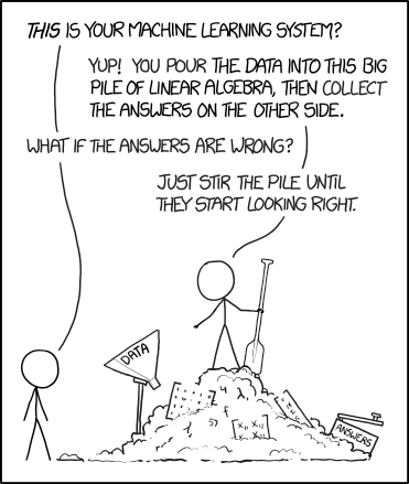
As an example of how useful this sort of partial automation can sometimes be for people who write code for a living, look at the timeline visualization at the top of this post. An LLM generated the skeleton code for that, and it did that in a fraction of the time it would take me to write that code myself. I was tweaking a functional python script within ~60s, eliminating maybe 45 minutes of dull work pulling together some boilerplate plot code. Likewise for the CAD kernel plot, which is obscure enough matplotlib code that it would have taken me a while to write by hand.
I think of this as effectively being another input mode for interacting with the computer—I can give explicit instructions via commands and with my cursor, or I can give woolly commands to an LLM and ask it to fill in the blanks. This output would be utterly, and I mean utterly useless if I were not able to go back and edit the code it had generated to fit my needs, but I can.
Code CAD, multimodal input, and the design bottleneck
With new input modes and possibilities for higher bandwidth input, the CAD bottleneck may no longer lie in getting design intent from the user. At least in the coming years, our input modes are going to be:
- GUI.
- Code.
- Natural language via AI.
The reality is that none of these input modalities will win alone. Today, most of the world's most complicated geometries are created by CAD power-users; people who've been using CATIA or NX for decades, and who are effectively subject matter experts in both geometry creation and their CAD package. However, these tools are also poorly suited to some incredibly important tasks. If you're working on highly iterative and programmatically driven designs, like we see in nuclear fusion and some aerospace applications, your hand will be effectively forced towards workflows that involve some degree of painful handoff between systems.
You may be generating gear profiles or magnet core shapes in custom software, then exporting profiles and point clouds to an intermediate format, then manually importing these and reassembling them in your CAD system. Or, you may be using OpenSCAD to handle the programmatically driven part of your workflow, then exporting STLs or 3MFs, then manually importing these and integrating them into your design.
Neither of these options are great. Both approaches are dripping in compromise, can be both slow and error-prone, and offer limited possibility for deep integration of LLMs or other AI tools.
Instead, we must seek to offer truly multimodal input. We need a single system that can support all of these together. We need the capacity for simultaneous GUI input, code input, and first-class API access for integration with other tools. No matter the input mode, we also need the geometry to be indistinguishable from that created by a GUI power user; we need editable models with a full feature tree—a mesh is not good enough.
In this way, not only do we offer free choice of input modes which have been largely mutually exclusive until today, we also have a system which offers unrivaled suitability for the adoption of AI. With open APIs and code-driven geometry, we can build and deploy LLMs that can interact with the CAD system in a way that is not possible today. We open the door to models that can simultaneously generate geometry, infer design intent, and that can suggest and implement changes to geometry based on user request. After all of that, they can still produce models that can be modified, corrected, and extended by the user.
By adopting this paradigm, we can begin to use natural language input as a means of accelerating human-guided product development; not just offering one-shot shape generation and hoping for the best.
Why I'm excited about Zoo
Hard problems and smart people
This is a statement of the obvious, but building a new CAD system is hard. There is a good reason that most commercial CAD systems are built on Parasolid or ACIS.
However, to achieve Zoo's goals, I think there is legitimate need to build a new kernel. We might be choosing the hard path here, but when hard problems are actually worth attacking, this is a good thing. Hard problems are how you keep the brightest minds engaged.
The team is also stacked with smart people. I am not a credentialist, but it is comforting to see names like Silicon Graphics, Google, Microsoft, Cloudflare, Ansys, Northrop Grumman—and The White House—amongst the backgrounds of your colleagues. Thankfully, my experience with the team so far has routinely left me feeling like the dumbest person in the room, providing all the supporting evidence I need that these people are legit.
Domain expertise and the structure of the universe
I touched on this a little above, but both the generative AI and the 'hardware' spaces are foamy targets for investors right now. Unfortunately, many of the companies I've seen move into this space seem to have fairly rudimentary understanding of its vast, complex, and relatively high-capability nature. Companies promising that they can generate CAD from natural language, but whose products produce polygonal mesh by tying an open source project to an OpenAI endpoint, either simply do not understand the requirements of real engineering teams—or they're cynically riding a hype cycle with no legitimate desire to address customer need.
At the risk of both repeating myself and sounding combative, an STL file is not really CAD: it can't be driven parametrically, and it can't be used to produce manufacturing drawings. For your product to have any prospect of being useful to real engineers who engage with real manufacturing techniques, where engineers are actually providing real GD&T and real drawings, your system must be capable of generating a B-rep† format one way or another.
Because the team at Zoo has real, lived experience of design and manufacture in-house, this sort of thing is understood throughout the company. In the handful of weeks I've been with the team, I have seen software teams not only battle with the structure of the universe, fighting some of the hardest problems in computational geometry, but also corral the mechanical engineers we have on staff and press them for feedback, seeking understanding of thought patterns, workflows, and common frustrations with their former CAD systems of choice.
They get it.
†Work on implicits is exciting, but I'm yet to see an implicit-based system that can meet all of our needs.
Work worth doing
This is effectively a rephrasing of Why our design tools matter, but I very sincerely believe that we need better, more open, and easier to use tools in engineering. We are surrounded by machines with incredible capabilities, and we simply aren't making the most of them.
Engineers craft the world, and I can think of few things I'd rather dedicate my time to more than supporting them to do just that—make better use of each other's technology to do a better job, faster, and with less frustration.
