Edge references
- Why edges are described by faces
- Two side faces
- Split edges and one end face
- Two end faces
- Final disambiguation with
index - Surface edges
In the Sketch on Face chapter, we saw how to reference faces of a solid. This chapter dives into how we can reference edges in a solid. KCL programmers need to reference edges for many reasons:
- Applying fillets or chamfers
- Applying an annotation, like a Geometric Dimensioning and Tolerancing (GD&T) callout
- Getting the length of an edge, for use in later calculations
- Extruding a sketch until it touches the chosen edge
But before we can apply any of these fun operations to edges, we first have to learn how to reference an edge. Then we can use those edges as arguments to the operations above.
Why edges are described by faces
An edge reference selects edges by describing the faces around them. Faces are generally more stable and predictable than edges after modeling operations, so face-based references make edge selection more robust.
An edge reference starts with sideFaces: the faces adjacent to each side of the edge. It can add endFaces and, rarely, an index until the reference identifies the intended edge or edges. Operations such as fillet, chamfer, revolve, helix, and mirror3d all use the same reference shape.
sideFacesfinds edges shared by the listed adjacent faces.endFacesnarrows those matches to edges that end at the listed faces.indexchooses one edge when the face information still produces multiple matches.
The examples below move from the common case to situations where an edge selection needs additional disambiguation. Each example includes the geometry needed to create that particular case, but the part to focus on is the small object passed to edges (gdt:annotation or fillet). Its face values are tags created earlier in each example.
Two side faces
Start with the simplest case: on an extruded rectangle, two side faces are enough to identify an edge. The sketch-segment names provide tags for the four walls, while tagStart and tagEnd create tags for the two caps.
@settings(defaultLengthUnit = mm, kclVersion = 2.0)

square = sketch(on = XY) {
  bottom = line(start = [0, 0], end = [20, 0])
  right = line(start = [20, 0], end = [20, 20])
  top = line(start = [20, 20], end = [0, 20])
  left = line(start = [0, 20], end = [0, 0])
}
squareRegion = region(segments = [square.left, square.bottom])
cube = extrude(
  squareRegion,
  length = 20,
  tagStart = $startCap,
  tagEnd = $endCap,
)

gdt::annotation(
  edges = [{ sideFaces = [squareRegion.tags.bottom, endCap] }],
  annotation = "Two side faces",
  framePosition = [12, 8],
  fontSize = 3.5,
)

hide(square)
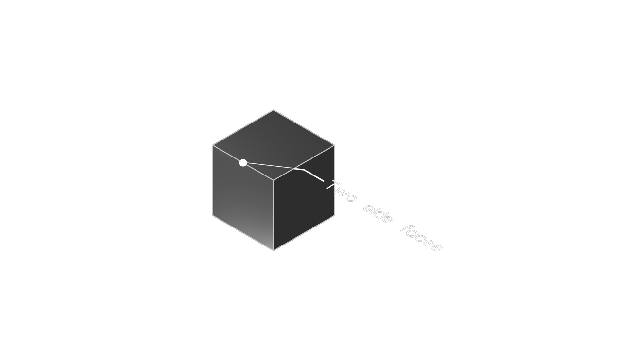
The selection to focus on is edges = [{ sideFaces = [squareRegion.tags.bottom, endCap] }]. It selects the edge shared by the wall created from bottom and the extrusion's end cap. The order of the faces does not matter. Any edge on this cube can be selected with the appropriate pair of face tags.
Split edges and one end face
A modeling operation can split an edge into several edges. The longer setup in this example creates that situation: two resulting edges have the same sideFaces. To select only one of them, the reference also supplies an endFaces entry. An end face touches the end of an edge rather than running alongside it.
@settings(defaultLengthUnit = mm, kclVersion = 2.0)

sketch001 = sketch(on = XZ) {
  line1 = line(start = [0.8, 0.57], end = [4.38, 0.43])
  line2 = line(start = [4.38, 0.43], end = [2.16, 4.94])
  line3 = line(start = [2.16, 4.94], end = [0.8, 0.57])
}
region001 = region(segments = [sketch001.line3, sketch001.line1])
extrude001 = extrude(region001, length = 5, tagStart = $capStart001)

sketch002 = sketch(on = -YZ) {
  line1 = line(start = [0.96, 6.38], end = [2.59, 2.41])
  line2 = line(start = [2.59, 2.41], end = [3.4, 6.25])
  line3 = line(start = [3.4, 6.25], end = [0.96, 6.38])
}
region002 = region(segments = [sketch002.line3, sketch002.line1])
extrude002 = extrude(region002, length = -20)
solid001 = subtract(extrude001, tools = extrude002)

gdt::annotation(
  edges = [{
    sideFaces = [region001.tags.line2, region001.tags.line3],
    endFaces = [capStart001],
  }],
  annotation = "One end face",
  framePosition = [4, 3],
  fontSize = 1,
)

hide(sketch001)
hide(sketch002)
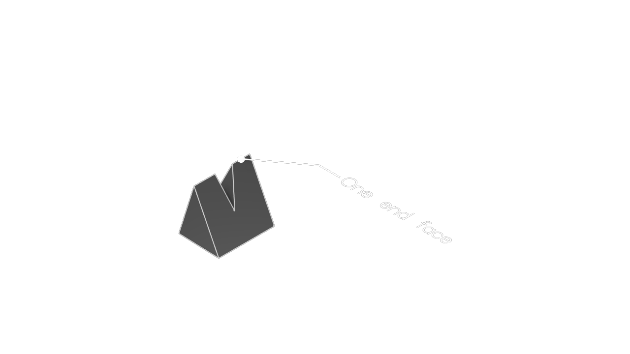
The selection to focus on is the object containing the two sideFaces plus endFaces = [capStart001]. Both candidate edges share the side faces, but only the intended edge touches capStart001, so the end face narrows the result to one edge.
An edge reference does not always have to resolve to one edge. Some operations deliberately accept multiple matches. The next example uses the same geometry but omits endFaces; the sideFaces pair therefore selects both matching edges, and one fillet call fillets both of them:
@settings(defaultLengthUnit = mm, kclVersion = 2.0, experimentalFeatures = allow)

sketch001 = sketch(on = XZ) {
  line1 = line(start = [0.8, 0.57], end = [4.38, 0.43])
  line2 = line(start = [4.38, 0.43], end = [2.16, 4.94])
  line3 = line(start = [2.16, 4.94], end = [0.8, 0.57])
}
region001 = region(segments = [sketch001.line3, sketch001.line1])
extrude001 = extrude(region001, length = 5)

sketch002 = sketch(on = -YZ) {
  line1 = line(start = [0.96, 6.38], end = [2.59, 2.41])
  line2 = line(start = [2.59, 2.41], end = [3.4, 6.25])
  line3 = line(start = [3.4, 6.25], end = [0.96, 6.38])
}
region002 = region(segments = [sketch002.line3, sketch002.line1])
extrude002 = extrude(region002, length = -20)
solid001 = subtract(extrude001, tools = extrude002)

fillet001 = fillet(
  solid001,
  edges = [{
    sideFaces = [region001.tags.line2, region001.tags.line3]
  }],
  radius = 0.2,
)

hide(sketch001)
hide(sketch002)
Two end faces
One end face is not always enough to resolve a single edge. The setup in the following example creates three edges with the same two side faces. Each circular cutter creates an end face that touches two of those edges, so the reference needs both end faces to select only the middle edge.
@settings(defaultLengthUnit = mm, kclVersion = 2.0)

circleSketch = sketch(on = -XZ) {
  circle1 = circle(start = [5.65, 5.03], center = [3.75, 3.53])
}
circleRegion = region(segments = [circleSketch.circle1])
cylinder = extrude(circleRegion, length = 5)

wedgeSketch = sketch(on = YZ) {
  line1 = line(start = [0.53, -1.43], end = [2.31, 3.36])
  line2 = line(start = [2.31, 3.36], end = [5.04, -2.99])
  line3 = line(start = [5.04, -2.99], end = [0.53, -1.43])
}
wedgeRegion = region(segments = [wedgeSketch.line1, wedgeSketch.line2], direction = CW)
wedge = extrude(wedgeRegion, length = -20)
solid001 = intersect([wedge, cylinder])

cutSketch = sketch(on = -XZ) {
  line1 = line(start = [var 1.32, var 3.62], end = [var 3.47, var 3.7])
  line2 = line(start = [var 3.85, var 3.56], end = [var 5.7, var 3.53])
  arc1 = arc(start = [var 4.04, var 3.56], end = [var 5.39, var 3.54], center = [var 4.72, var 3.82])
  coincident([arc1.start, line2])
  coincident([arc1.end, line2])
  arc2 = arc(start = [var 1.67, var 3.63], end = [var 3.18, var 3.69], center = [var 2.42, var 3.83])
  coincident([arc2.start, line1])
  coincident([arc2.end, line1])
}
cutRegion1 = region(segments = [cutSketch.arc1, cutSketch.line2])
cut1 = extrude(cutRegion1, length = 5)
cutRegion2 = region(segments = [cutSketch.arc2, cutSketch.line1])
cut2 = extrude(cutRegion2, length = 5)
solid002 = subtract(solid001, tools = cut1)
solid003 = subtract(solid002, tools = cut2)

gdt::annotation(
  edges = [{
    sideFaces = [wedgeRegion.tags.line1, wedgeRegion.tags.line2],
    endFaces = [cutRegion1.tags.arc1, cutRegion2.tags.arc2],
  }],
  annotation = "Two end faces",
  framePosition = [4, 3],
  fontSize = 0.5,
)

hide(circleSketch)
hide(wedgeSketch)
hide(cutSketch)
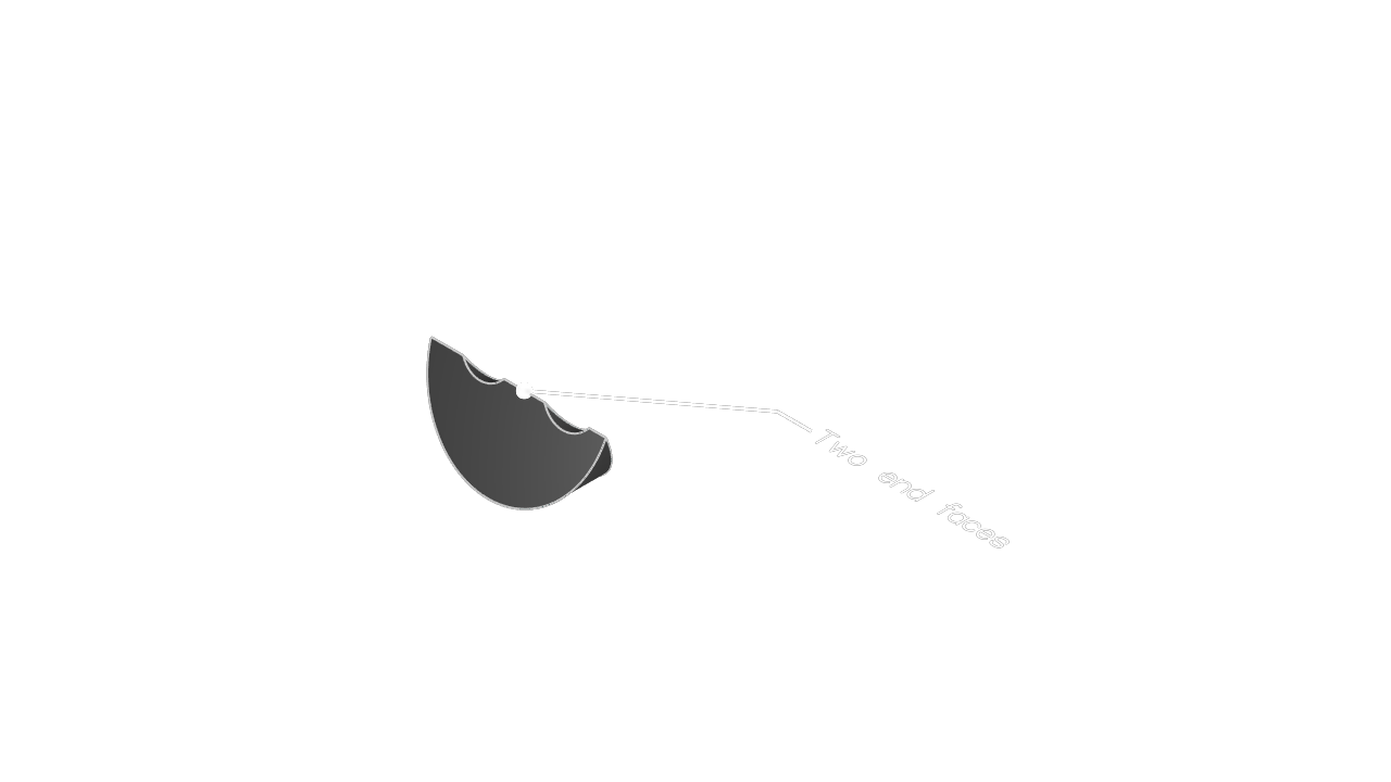
The selection to focus on combines sideFaces with two entries in endFaces. The first end face rules out one candidate and the second rules out the other, leaving exactly one edge.
Final disambiguation with index
In rare topologies, multiple edges can share every useful side and end face. The setup below creates two such matches. Because face information cannot distinguish them, the reference uses the zero-based index field to select one of the matching edges.
@settings(defaultLengthUnit = mm, kclVersion = 2.0)

circleSketch = sketch(on = -XZ) {
  circle1 = circle(start = [5.65, 5.03], center = [3.75, 3.53])
}
circleRegion = region(segments = [circleSketch.circle1])
cylinder = extrude(circleRegion, length = 5)

wedgeSketch = sketch(on = YZ) {
  line1 = line(start = [0.53, -1.43], end = [2.31, 3.36])
  line2 = line(start = [2.31, 3.36], end = [5.04, -2.99])
  line3 = line(start = [5.04, -2.99], end = [0.53, -1.43])
}
wedgeRegion = region(segments = [wedgeSketch.line1, wedgeSketch.line2], direction = CW)
wedge = extrude(wedgeRegion, length = -20)
solid001 = intersect([wedge, cylinder])

cutSketch = sketch(on = -XZ) {
  line1 = line(start = [var 1.32, var 3.62], end = [var 3.47, var 3.7])
  line2 = line(start = [var 3.85, var 3.56], end = [var 5.7, var 3.53])
  arc1 = arc(start = [var 4.04, var 3.56], end = [var 5.39, var 3.54], center = [var 4.72, var 3.82])
  coincident([arc1.start, line2])
  coincident([arc1.end, line2])
}
cutRegion = region(segments = [cutSketch.arc1, cutSketch.line2])
cut = extrude(cutRegion, length = 5)
solid002 = subtract(solid001, tools = cut)

gdt::annotation(
  edges = [{
    sideFaces = [wedgeRegion.tags.line1, wedgeRegion.tags.line2],
    index = 1,
  }],
  annotation = "Index 1",
  framePosition = [4, 3],
  fontSize = 0.8,
)

hide(circleSketch)
hide(wedgeSketch)
hide(cutSketch)
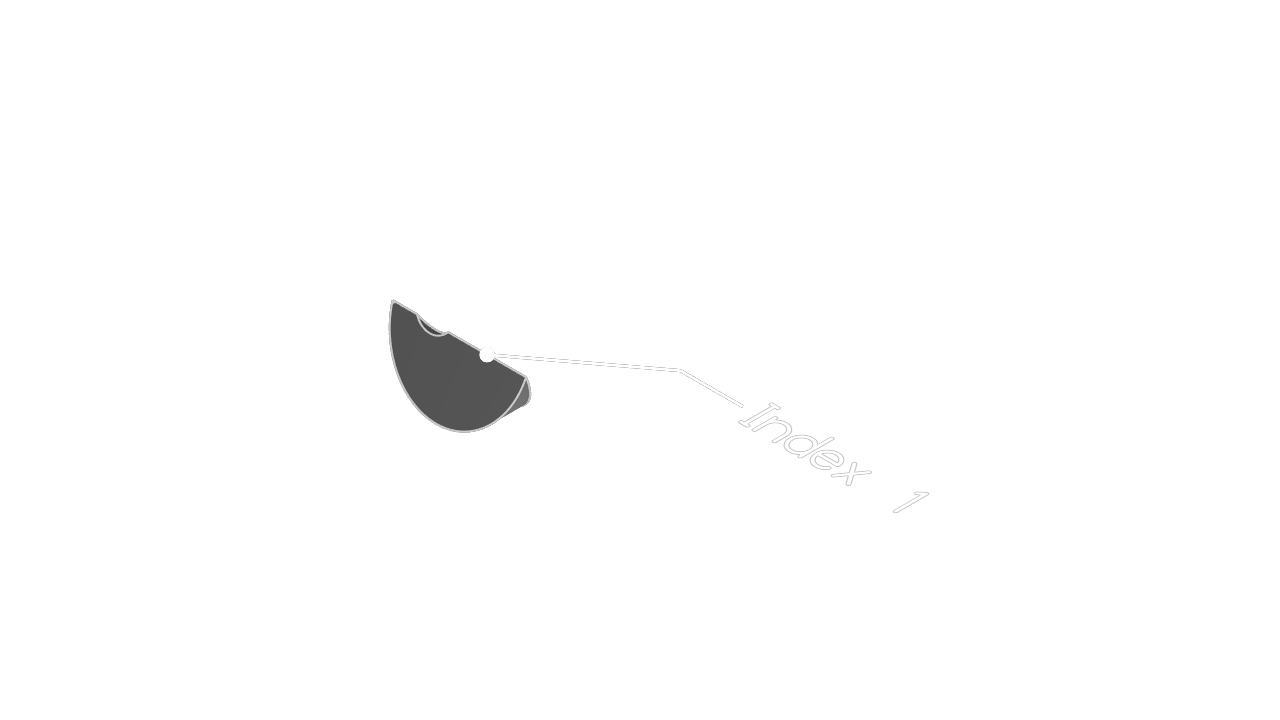
The selection to focus on uses the shared sideFaces and adds index = 1, selecting the second matching edge. Prefer face information whenever it can identify the intended edge, and use index only when the geometry leaves indistinguishable matches. Face-based references express the geometric relationship and are therefore more robust.
Surface edges
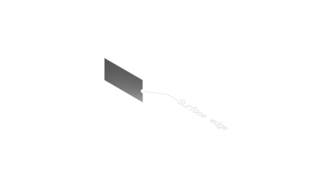
A surface body does not enclose a volume, so a boundary edge may have only one side face and no useful end faces. In this example all of the boundary edges belong to the same surface face, so the reference uses that one sideFaces entry and index to select a particular boundary edge:
@settings(defaultLengthUnit = mm, kclVersion = 2.0)

surfaceSketch = sketch(on = XY) {
  source = line(start = [0, 0], end = [20, 0])
}
surface = extrude(
  surfaceSketch.source,
  length = 10,
  bodyType = SURFACE,
  method = NEW,
)

gdt::annotation(
  edges = [{
    sideFaces = [surface.sketch.tags.source],
    index = 1,
  }],
  annotation = "Surface edge",
  framePosition = [8, 5],
  fontSize = 2,
)

hide(surfaceSketch)